JN5148-EK010 Jennic LTD, JN5148-EK010 Datasheet - Page 19
JN5148-EK010
Manufacturer Part Number
JN5148-EK010
Description
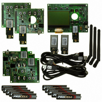
KIT EVAL ZIGBEE PRO JN5148
Manufacturer
Jennic LTD
Series
JN5148r
Type
Transceiverr
Specifications of JN5148-EK010
Frequency
2.4GHz
Silicon Manufacturer
Jennic
Silicon Core Number
JN5148
Kit Contents
SDK, User Guides, Reference Manual
Silicon Family Name
Zigbee PRO
Features
Rapid Application Development And Demonstration
Lead Free Status / RoHS Status
Lead free / RoHS Compliant
For Use With/related Products
ZigBee Pro
Lead Free Status / RoHS Status
Lead free / RoHS Compliant, Lead free / RoHS Compliant
Other names
616-1044
935294044596
JN5148-EK010
935294044596
JN5148-EK010


3. Home Sensor Demonstration
JN-UG-3062 v2.1
3.1 Demo System Overview
You are now going to set up a small wireless network, using the contents of the
JN5148-EK010 Evaluation Kit, and run the JenNet Home Sensor Demonstration
application that has been pre-programmed into the Flash memory devices of the
boards.
This chapter guides you through the set-up and operation of the demo system, as
follows:
The Home Sensor Demonstration uses the boards of the evaluation kit to form a
system for monitoring environmental conditions in a small building, typically a house
or apartment, with the boards placed in different rooms. Each board is equipped with
a temperature sensor, a humidity sensor and a light-level sensor. Measurements from
the Sensor boards are periodically sent to the Controller board, where they can be
displayed on this board’s LCD screen. The demonstration also provides lighting
control functionality, in which buttons on a Sensor board can be used to control an
LED on the Controller board.
The evaluation kit boards are pre-programmed as the following network devices for
the purpose of this demonstration:
The demonstration can use four boards or all five boards from the evaluation kit, but
in either case only four boards can provide sensor measurements (see
The precise topology of the wireless network cannot be pre-determined since the
network is formed dynamically. An example system consisting of four boards is shown
in
operation of the demonstration.
Figure 11
1.
2.
3.
4.
5.
The Contoller board (with LCD screen) is programmed as the Co-ordinator.
The two Sensor boards with SMA connectors are programmed as Routers.
The two Sensor boards with integrated PCB antennae are programmed as End
Devices.
In the case of four boards (default mode), the sensor measurements of the
Controller board are used.
In the case of five boards, the sensor measurements of the Controller board
are not used (this board acts only as the network Co-ordinator and display unit)
Section 3.1
functionality and its physical components.
Section 3.2
evaluation kit and run the Home Sensor Demonstration.
Section 3.3
Section 3.4
Section 3.5
below. However, the exact system topology is not important for the
details how to set up the wireless network from the contents of the
provides an overview of the demo system, describing its
describes how to use the demo for sensor monitoring.
describes how to use the lighting control feature of the demo.
describes how to perform a routing experiment with the demo.
© NXP Laboratories UK 2010
JN5148-EK010 Evaluation Kit
Section
User Guide
3.3.4):
19
Related parts for JN5148-EK010
Image
Part Number
Description
Manufacturer
Datasheet
Request
R

Part Number:
Description:
KIT UPGRADE ZIGBEE PRO
Manufacturer:
Jennic LTD
Datasheet:

Part Number:
Description:
32BIT, MCU, ZIGBEE PRO, 128K RAM, 56QFN
Manufacturer:
Jennic LTD
Datasheet:

Part Number:
Description:
MODULE, ZIGBEE PRO, W/INTEGRATED ANT
Manufacturer:
Jennic LTD
Part Number:
Description:
MODULE, ZIGBEE PRO, HI-PWR W/UFL ANT
Manufacturer:
Jennic LTD

Part Number:
Description:
KIT EVAL IEEE802.15.4 JN5139
Manufacturer:
Jennic LTD
Datasheet:

Part Number:
Description:
MODULE ZIGBEE CERM ANT JN5139
Manufacturer:
Jennic LTD
Datasheet:

Part Number:
Description:
32BIT MCU, ZIGBEE, 192K ROM, 5139
Manufacturer:
Jennic LTD
Datasheet:

Part Number:
Description:
ZigBee Module W/ Integrated Antenna
Manufacturer:
Jennic LTD
Datasheet:

Part Number:
Description:
ZigBee Module W/ SMA Connector
Manufacturer:
Jennic LTD
Datasheet:

Part Number:
Description:
ZigBee Extended Range Module W/ SMA Connector
Manufacturer:
Jennic LTD
Datasheet:

Part Number:
Description:
ZigBee Extended Range Module W/ UFI Connector
Manufacturer:
Jennic LTD
Datasheet:
Part Number:
Description:
32BIT MCU, ZIGBEE, 192K ROM, 5139
Manufacturer:
Jennic LTD
Datasheet:
Part Number:
Description:
32BIT, MCU, ZIGBEE PRO, 128K RAM, 56QFN
Manufacturer:
Jennic LTD
Datasheet: