101-1165 Rabbit Semiconductor, 101-1165 Datasheet - Page 7
101-1165
Manufacturer Part Number
101-1165
Description
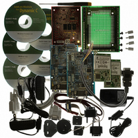
KIT WIRELESS CONTROL APP 2.4GHZ
Manufacturer
Rabbit Semiconductor
Type
RabbitWeb Moduler
Specifications of 101-1165
Frequency
2.4GHz
Wireless Frequency
7.4 MHz
Modulation
FHSS
For Use With/related Products
Rabbit-based Boards
Lead Free Status / RoHS Status
Lead free / RoHS Compliant
Other names
316-1132


Wireless Data Module Setup
1. Set the DIP switches on both RS-232/RS-485 Interface
2. Mount each wireless data module to an RS-232/RS-485
3. Use the DB9F to DB9M serial cable to connect one
4. Locate and double-click setup_x-ctu.exe in the Dynamic C DCRabbit…\X-CTU software
5. Connect a 9 V AC adapter to the power input on the RS-232/RS-485 Interface Board. Use the ON/OFF
6. Start X-CTU from the desktop icon and set the “PC Settings” tab to 38400 baud (XCite™ module) or
7. Click Read on the “Modem Configuration” tab. The modem type identified in the previous step should
8. Now set the “PC Settings” tab to 9600 baud, NONE flow control (Modbus sample program) or
Boards to the RS-232 Mode [Switch 1 is ON (up) and
the remaining 5 switches are OFF (down)].
Interface Board as shown at right.
Interface Board to your PC COM port. You may use
the RS-232/USB converter (Part No. 540-0070) if your
PC does not have a COM port.
directory to install the X-CTU application that you will use to set up the wireless data modules.
switch on the RS-232/RS-485 Interface Board to turn the Interface Board on— the red LED should light
up.
19200 baud (XStream™ module), NONE flow control, 8 data bits, parity NONE, 1 stop bit. Click
Test/Query, then click OK when you get the report “Communication with modem…OK” that displays
the modem type and firmware. Note the modem type (XC09-038 or X24-019). The settings in this step
apply only when you have a module “fresh out of the box” — otherwise use the settings in Step 8.
display, and you will now set the serial options. Click Write when you have set the serial options.
HARDWARE flow control (other sample programs), 8 data bits, parity NONE, 1 stop bit. Click Test/
Query, then click OK when you get the report “Communication with modem…OK” that displays the
modem type and firmware.
• AT Command/Serial Interface Options
• Non-AT Settable Parameters/Serial Interfacing Options
CD – D03 Configuration = 2 - low
Baud Rate = 3 - 9600
DI2 Configuration = 0 - Disable (Modbus only)
SWITCH
ON/OFF
NOTE: The D12 configuration varies depending on whether you will be working with the
MODBUS_SERIAL_SLAVE.C or the PPP sample programs. Remember to reconfigure the
wireless data module following Steps 7–8 when changing between these sample programs.
LEDs
XC09-038 (XCite™)
= 1 - RTS flow control (PPP only)
CONNECTOR
SERIAL
POWER
INPUT
022-0115 Rev. A
• Networking
• Serial Interfacing Options
RR – Retries = FF
BD – Interface Data Rate = 3 - 9600
RT – DI2 Configuration = 0 - Disable (Modbus only)
CD – D03 Configuration = 2 - low
Config
button
O
N
RS-232/RS-485
1 2 3 4 5 6
Interface
Board
X24-019 (XStream™)
= 2 - RTS flow control (PPP only)
RF Module
7
Related parts for 101-1165
Image
Part Number
Description
Manufacturer
Datasheet
Request
R

Part Number:
Description:
KIT DEV FOR BL2500 COYOTE
Manufacturer:
Rabbit Semiconductor
Datasheet:

Part Number:
Description:
KIT APPLICATION SIMPLE SENSOR
Manufacturer:
Rabbit Semiconductor
Datasheet:

Part Number:
Description:
KIT DEV RCM5400W US/INTERNATIONL
Manufacturer:
Rabbit Semiconductor
Datasheet:

Part Number:
Description:
DEV KIT DELUXE MINICORE RCM5600W
Manufacturer:
Rabbit Semiconductor
Datasheet:


Part Number:
Description:
KIT FOR BL4S100 STARTER PACKAGE
Manufacturer:
Rabbit Semiconductor
Datasheet:

Part Number:
Description:
DEV KIT STANDARD MINI RCM5600W
Manufacturer:
Rabbit Semiconductor
Datasheet:

Part Number:
Description:
KIT ADD ON WI-FI RCM3400
Manufacturer:
Rabbit Semiconductor
Datasheet:

Part Number:
Description:
KIT MESH NETWORK ADD-ON RCM4510W
Manufacturer:
Rabbit Semiconductor
Datasheet:

Part Number:
Description:
MODULE RABBITCORE RCM3720
Manufacturer:
Rabbit Semiconductor
Datasheet:
Part Number:
Description:
MODULE RABBITCORE RCM3220
Manufacturer:
Rabbit Semiconductor
Datasheet:
Part Number:
Description:
MODULE RABBITCORE RCM3210
Manufacturer:
Rabbit Semiconductor
Datasheet:
Part Number:
Description:
COMPUTER SGL-BOARD OP6600 W/SRAM
Manufacturer:
Rabbit Semiconductor
Datasheet:
Part Number:
Description:
COMPUTER SGL-BD BL2000 SRAM/FLSH
Manufacturer:
Rabbit Semiconductor