101-1165 Rabbit Semiconductor, 101-1165 Datasheet
101-1165
Specifications of 101-1165


Related parts for 101-1165


101-1165 Summary of contents
Page 1
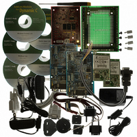
... The Wireless Control Application Kit highlights the interface of MaxStream’s 900 MHz XCite™ or 2.4 GHz XStream™ wireless data modules with one of Rabbit Semiconductor’s single-board computers, the LP3500. The Wireless Control Application Kit comes with sample programs that illustrate the simple con- figuration and control of a new or existing Rabbit-based embedded system via a wireless interface using either the Modbus protocol or a direct point-to-point protocol (PPP) serial connection with a Web browser ...
Page 2
Table 1 compares the features of the MaxStream 900 MHz XCite™ and 2.4 GHz XStream™ RF modules used in the Wireless Control Application Kits. Table 1. Maxstream RF Modules in Wireless Control Application Kit Feature Frequency Indoor Range Outdoor Line-of ...
Page 3
Application Kit Features • LP3500 single-board computer with LP3500 Prototyping Board • Two 900 MHz XCite™ or two 2.4 GHz XStream™ RF modules with two MaxStream RS-232/RS-485 Interface Boards • Dynamic C CDs for RabbitWeb module, Point-to Point Protocol (PPP) ...
Page 4
Hardware Setup The Wireless Control Application Kit Getting Started instructions included with the Application Kit shows how to set up and program the LP3500 with its Prototyping Board, then interface it wirelessly with your PC via MaxStream’s 900 MHz XCite™ ...
Page 5
... Connect the other end of the programming cable to a COM port on your PC. NOTE: Be sure to use the programming cable (Part No. 101-0513) supplied with this Appli- cation Kit—the programming cable has red shrink wrap around the RS-232 converter section located in the middle of the cable. ...
Page 6
Connect Power Supply Hook up the connector from the adapter to header J5 on the Prototyping Board as shown above. The orientation of this connector is not important since the VIN (positive) voltage is the middle pin, ...
Page 7
Wireless Data Module Setup 1. Set the DIP switches on both RS-232/RS-485 Interface Boards to the RS-232 Mode [Switch (up) and the remaining 5 switches are OFF (down)]. 2. Mount each wireless data module to an RS-232/RS-485 ...
Page 8
Turn the Interface Board OFF, then use the DB9M to bare wire leads serial cable to connect this Interface Board to header J41 on the LP3500 Prototyping Board. Turn the Interface Board back ON. 10. Connect the other Interface ...
Page 9
Wireless Control Demonstrations You are now ready to access the LP3500 from your PC through a wireless interface instructions depend on the sample program you loaded on the LP3500. Appendix A documents the use of the Dynamic C function calls ...
Page 10
DIRECT_PPP.C and DIRECT_PPP_HTTP.C Before accessing the LP3500 wirelessly, you will have to configure your PC or notebook. If the PC or note- book is connected to a network recommended that you disconnect it from the network. The screen ...
Page 11
Set Up Network Connection the control panel (Start > Settings > Control Panel) and double-click the Network Con- nections icon. 2. Click the “New Connection Wizard,” then press Next to bring up the New Connection Wizard. 3. ...
Page 12
If you are running DIRECT_PPP_HTTP.C on the LP3500, you may also ping the LP3500 to demonstrate the PPP wireless connection following the above instructions. You may also open your Web browser and enter the following URL to interface wirelessly with ...
Page 13
... Dynamic C CD and the supplemental CD for this application kit. LP3500 User’s Manual XCite™ RF Module Product Manual XStream™ RF Module Product Manual Check the Rabbit Semiconductor versions of supporting documentation. MaxStream has several documents dealing with RF signal losses, RF installation tips, and selecting a radio frequency. Indoor Path Loss Maximizing Range 900 MHz vs 2 ...
Page 14
Appendix A — Software Reference Sample Programs MODBUS_SERIAL_SLAVE.C Let’s examine some of the code in the MODBUS_SERIAL_SLAVE.C sample program. In this sample program, the LP3500 is the slave device, and the PC is the master. Macro Definitions #define MODBUS_DEBUG_PRINT 0 ...
Page 15
DIRECT_PPP_HTTP.C Let’s examine some of the code in the DIRECT_PPP_HTTP.C sample program. In this sample program, the LP3500 will be the host device, which means that it will wait for the guest device to begin the PPP ses- sion. Once ...
Page 16
This block of code specifies the LP3500, and assigns the serial ports — Serial Port C is used for the PPP connection. An alternate serial port configuration is provide for the RCM3720 RabbitCore module, which may also be used without ...
Page 17
RabbitWeb Macros #define USE_RABBITWEB 1 #define SSPEC_MAXNAME 32 #define HTTP_MAXSERVERS 1 The USE_RABBITWEB macro is defined use the HTTP server enhancements. The SSPEC_MAXNAME macro defines the maximum length of mime type (default = 20), and the macro ...
Page 18
The loadStatus function displays that we are getting the lp3500.htm page. While all this is happing, a script is called ...
Page 19
Digital Outputs The control of the 10 digital outputs through the RabbitWeb interface is governed by the digOutSetup, digOutLabels, digOutStatus, and digOutUpdate function calls. You would simply change the name or add additional labels to digOutLabels to match the relays ...
Page 20
The anaInVolts() function call reads each of the eight analog inputs, and in turn converts each raw reading to a voltage; the first parameter in anaInVolts() is the channel number (0–7), and the second parameter is ...
Page 21
Analog Outputs The control of the three analog outputs through the RabbitWeb interface is governed by the anaOutSetup, anaOuts, anaOutStatus, and anaOutUpdate function calls. The anaOutSetup function call is used to assign the Analog Outputs name to the group header ...
Page 22
... Complete specifications for the LP3500 and the LP3500 Prototyping Board are available in the LP3500 User’s Manual. Figure A-1. RS-232/RS-485 Interface Board Dimensions (with Wireless Data Module Installed) NOTE: All measurements are in inches followed by millimeters enclosed in parentheses. All dimensions have a manufacturing tolerance of ±0.01" (0.25 mm). Rabbit Semiconductor Inc. www.rabbit.com 022-0115 Rev ...