ATAKSTK511-9 Atmel, ATAKSTK511-9 Datasheet - Page 36
ATAKSTK511-9
Manufacturer Part Number
ATAKSTK511-9
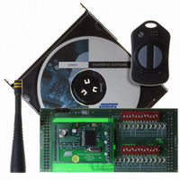
Description
KIT RF MODULE 915MHZ FOR STK500
Manufacturer
Atmel
Series
SmartRF®r
Type
Transmitter, Receiver, ASK, FSKr
Specifications of ATAKSTK511-9
Frequency
915MHz
Wireless Frequency
915 MHz
Modulation
ASK, FSK
Operating Voltage
5 V
Antenna
External Whip
For Use With/related Products
ATSTK500
Lead Free Status / RoHS Status
Contains lead / RoHS non-compliant


STK511 User Guide
Table 7-1. Troubleshooting Solutions (Continued)
Problem
Transmitter Application Board
LED(s) constantly lit
Unable to program Transmitter
Application board through ISP
header
Demo not working (STK500 LED(s)
not responding to transmitted
signal)
Reason
Demo Software corrupted
Incorrect orientation of the ribbon
cable connecting the ISP header to
the STK500
Power not supplied to transmitter
on-board microcontroller
Wrong device selected in the
STK500 software
Power and serial cable not
connected to STK500
Incorrect orientations of the
Receiver Application Board or
Receiver Interface Board
Power not properly supplied to all
boards
Data Selector switch not set to
STK500 position
Microcontroller socket on STK500
not populated
Corrupted software in the STK500
microcontroller
10-pin ribbon cable not connected
properly
Incompatible modulation used on
the transmitter and receiver
CdS Photocell covered
Receiver set to permanent sleep
Receiver limits incorrect
Receiver antenna not connected
Solution
Reload the desired software
according to section
Description” on page 4-6
Verify the orientation of both sides
of the ribbon cable
Supply 3 volts to the transmitter
microcontroller through the coin cell
battery or via the STK500
Select ATtiny13 from the Device
menu. Verify that the signature byte
matches in the Advanced tab
Verify setup of the STK500
hardware
Verify the hardware is assembled
correctly as shown in chapter 1
See troubleshooting section for
each board.
Set the switch to the proper position
and re-run the demo
The demo uses an AT90S8515
microcontroller in the STK500 to
decode the received signal
Reload the Receiver Decode
software as shown in
on page 2-2
Verify that the 10-pin ribbon cable is
properly connected to the LEDS
header from the PORTC header on
the STK500
Verify that transmitter and receiver
are both set for the same
modulation type (ASK versus FSK)
The LED(s) on the STK500 are only
active when the CdS Photocell is
subjected to a light source and one
of the buttons has been pressed
Check for Sleep bits in the
OPMODE register set for all 1
Verify correct register settings as
given in chapter 1
Connect external whip antenna to
Receiver Application Board
Troubleshooting Guide
“Software
Figure 2-1
4842B–AVR–10/09
7-3
Related parts for ATAKSTK511-9
Image
Part Number
Description
Manufacturer
Datasheet
Request
R

Part Number:
Description:
DEV KIT FOR AVR/AVR32
Manufacturer:
Atmel
Datasheet:

Part Number:
Description:
INTERVAL AND WIPE/WASH WIPER CONTROL IC WITH DELAY
Manufacturer:
ATMEL Corporation
Datasheet:
Part Number:
Description:
Low-Voltage Voice-Switched IC for Hands-Free Operation
Manufacturer:
ATMEL Corporation
Datasheet:
Part Number:
Description:
MONOLITHIC INTEGRATED FEATUREPHONE CIRCUIT
Manufacturer:
ATMEL Corporation
Datasheet:
Part Number:
Description:
AM-FM Receiver IC U4255BM-M
Manufacturer:
ATMEL Corporation
Datasheet:
Part Number:
Description:
Monolithic Integrated Feature Phone Circuit
Manufacturer:
ATMEL Corporation
Datasheet:
Part Number:
Description:
Multistandard Video-IF and Quasi Parallel Sound Processing
Manufacturer:
ATMEL Corporation
Datasheet:
Part Number:
Description:
High-performance EE PLD
Manufacturer:
ATMEL Corporation
Datasheet:
Part Number:
Description:
8-bit Flash Microcontroller
Manufacturer:
ATMEL Corporation
Datasheet:
Part Number:
Description:
2-Wire Serial EEPROM
Manufacturer:
ATMEL Corporation
Datasheet: