ATAKSTK511-9 Atmel, ATAKSTK511-9 Datasheet - Page 25
ATAKSTK511-9
Manufacturer Part Number
ATAKSTK511-9
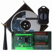
Description
KIT RF MODULE 915MHZ FOR STK500
Manufacturer
Atmel
Series
SmartRF®r
Type
Transmitter, Receiver, ASK, FSKr
Specifications of ATAKSTK511-9
Frequency
915MHz
Wireless Frequency
915 MHz
Modulation
ASK, FSK
Operating Voltage
5 V
Antenna
External Whip
For Use With/related Products
ATSTK500
Lead Free Status / RoHS Status
Contains lead / RoHS non-compliant


4842B–AVR–10/09
STK511 Transmitter Board
5.1.3
5-2
Functional Features
Figure 5-2.
Figure 5-3.
Using Atmel’s AVR Studio
on the accompanying CD can be easily loaded. The assembly-language code is well commented and
should enable the user to modify such things as the Manchester-encoded transmission data rate and
duty cycle, or the update interval for light-sensor.
Modulation Modes: The STK511 transmitter can be configured to modulate its RF carrier using either
ASK or FSK. Selection of either modulation scheme is defined by the software in the microcontroller,
which frees the user from having to change components on the PCB.
Data is modulated using Manchester-encoding at a 1 kHz data rate. At power up, the software is initial-
ized to support FSK. However, the modulation mode can be toggled between ASK and FSK by
simultaneously pressing and releasing both buttons on the transmitter. FSK is indicated when both LEDs
flash during data transmission while only one LED flashes during ASK.
ASK modulation occurs when the AVR enables the T5750/3/4 IC and sends a serial data stream to the
IC’s control input. In contrast, an FSK-modulated signal is generated when the AVR sends the serial
data stream to the crystal oscillator’s pair of load capacitors. The lower, shifted RF FSK frequency is
obtained by asserting an AVR I/O low which connects an additional load capacitance to the crystal oscil-
lator. When that same AVR control-port pin is set as a high-impedance input, the upper RF FSK
frequency (which is the same as the carrier frequency during ASK modulation) is generated.
WatchDog Timer: Another built-in feature of the ATtiny13 microcontroller, utilized in the STK511 trans-
mitter, is the WatchDog Timer (WDT). At time-out, the WDT can generate either a system-reset signal or
an interrupt, which can be handled by software Interrupt Service Routine. For example, in the Sensor
program (one of the demo programs on the accompanying CD), the WDT is programmed to generate an
interrupt that awakens the transmitter at one of two specified intervals (selectable by the user) in order to
measure light intensity on the CdS photocell. The WDT time-out interval can be defined within a range of
0.016 seconds to 8 seconds by setting bits in a control register.
6-pin ISP Header Pinout (Viewed from the Top of the Fob)
Transmitter Programming Assembly
®
software program and the STK500, for example, the demo software provided
STK511 User Guide
Related parts for ATAKSTK511-9
Image
Part Number
Description
Manufacturer
Datasheet
Request
R

Part Number:
Description:
DEV KIT FOR AVR/AVR32
Manufacturer:
Atmel
Datasheet:

Part Number:
Description:
INTERVAL AND WIPE/WASH WIPER CONTROL IC WITH DELAY
Manufacturer:
ATMEL Corporation
Datasheet:
Part Number:
Description:
Low-Voltage Voice-Switched IC for Hands-Free Operation
Manufacturer:
ATMEL Corporation
Datasheet:
Part Number:
Description:
MONOLITHIC INTEGRATED FEATUREPHONE CIRCUIT
Manufacturer:
ATMEL Corporation
Datasheet:
Part Number:
Description:
AM-FM Receiver IC U4255BM-M
Manufacturer:
ATMEL Corporation
Datasheet:
Part Number:
Description:
Monolithic Integrated Feature Phone Circuit
Manufacturer:
ATMEL Corporation
Datasheet:
Part Number:
Description:
Multistandard Video-IF and Quasi Parallel Sound Processing
Manufacturer:
ATMEL Corporation
Datasheet:
Part Number:
Description:
High-performance EE PLD
Manufacturer:
ATMEL Corporation
Datasheet:
Part Number:
Description:
8-bit Flash Microcontroller
Manufacturer:
ATMEL Corporation
Datasheet:
Part Number:
Description:
2-Wire Serial EEPROM
Manufacturer:
ATMEL Corporation
Datasheet: