ATAKSTK511-9 Atmel, ATAKSTK511-9 Datasheet - Page 28
ATAKSTK511-9
Manufacturer Part Number
ATAKSTK511-9
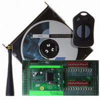
Description
KIT RF MODULE 915MHZ FOR STK500
Manufacturer
Atmel
Series
SmartRF®r
Type
Transmitter, Receiver, ASK, FSKr
Specifications of ATAKSTK511-9
Frequency
915MHz
Wireless Frequency
915 MHz
Modulation
ASK, FSK
Operating Voltage
5 V
Antenna
External Whip
For Use With/related Products
ATSTK500
Lead Free Status / RoHS Status
Contains lead / RoHS non-compliant


5.2
5.2.1
5.2.2
STK511 User Guide
Software Description
Overview
Sample Software
There are two sample programs included on the accompanying CD that demonstrate the transmitter's
functional capabilities. One called STK511 TX UpDown, increments and decrements a counter and
transmits the count value. The other, called STK511 TX Sensor, utilizes the integral CdS photocell as a
light-intensity sensor and sends an 8 bit digital value corresponding to the voltage measured across the
light sensor.
Button functionality specific to each program is included in the descriptions that follow.
1. STK511 TX UpDown senses right/left button presses and increments/decrements (respectively) a
2. STK511 TX Sensor demonstrates the capabilities of the A/D converter in the ATtiny13, using the
; - - - - - - - - - - - - - - - - - - - - - - - - - - - - - - - - - - - - -
; routine: Main
; calls: Setup, Snooze
; called by:
; function: main pgm
; - - - - - - - - - - - - - - - - - - - - - - - - - - - - - - - - - - - - -
Main:
counter in the ATtiny13. The count value is transmitted to the companion receiver upon button
release. With the receiver mated through the STK511 to the STK500, the count value is displayed (in
hexadecimal format) on the 8 LEDs of the STK500. When not transmitting the results of an incre-
ment/decrement command, the transmitter is in a low-current-consumption sleep mode.
CdS photocell as a light-intensity sensor. The resistance of the photocell’s output (which is inversely
proportional to the amount of light incident on the sensor) is converted to an input voltage signal to
the A/D converter. The resulting A/D conversion quantization is binned into one of eight value-
ranges, which is transmitted to the companion receiver mated to the STK511. The relative intensity
of the detected light is displayed in bar graph form on the 8 LEDs of the STK500 -- from right to left,
more lighted LED indicate higher light levels incident on the photocell. The two buttons on the trans-
mitter initiate periodic RF transmission of the binned A/D data, as well as determine the transmit
interval. Pressing the right button sets the transmit interval at 0.25 seconds; the left, at 8 seconds.
Sensor readings are sent for approximately 30 seconds, after which the transmitter enters a low-cur-
rent-consumption sleep mode. Periodic transmissions resume when either button is pressed.
RCALL
CPI
BRNE
LDI
OUT
LDI
OUT
Snooze
WDTcounter,0x00; TP - Check for 30 sec timeout here
KeepAlive
R16,0x50
WDTCR,R16
R16,0x00
WDTCR,R16
; Sleep
; TP - If not 30 sec loop but keep sleeping in
; TP - If 30 sec passed turn off the WD Timer
; TP - Sleep until button press starts WD Timer
between TX
STK511 Transmitter Board
4842B–AVR–10/09
5-5
Related parts for ATAKSTK511-9
Image
Part Number
Description
Manufacturer
Datasheet
Request
R

Part Number:
Description:
DEV KIT FOR AVR/AVR32
Manufacturer:
Atmel
Datasheet:

Part Number:
Description:
INTERVAL AND WIPE/WASH WIPER CONTROL IC WITH DELAY
Manufacturer:
ATMEL Corporation
Datasheet:
Part Number:
Description:
Low-Voltage Voice-Switched IC for Hands-Free Operation
Manufacturer:
ATMEL Corporation
Datasheet:
Part Number:
Description:
MONOLITHIC INTEGRATED FEATUREPHONE CIRCUIT
Manufacturer:
ATMEL Corporation
Datasheet:
Part Number:
Description:
AM-FM Receiver IC U4255BM-M
Manufacturer:
ATMEL Corporation
Datasheet:
Part Number:
Description:
Monolithic Integrated Feature Phone Circuit
Manufacturer:
ATMEL Corporation
Datasheet:
Part Number:
Description:
Multistandard Video-IF and Quasi Parallel Sound Processing
Manufacturer:
ATMEL Corporation
Datasheet:
Part Number:
Description:
High-performance EE PLD
Manufacturer:
ATMEL Corporation
Datasheet:
Part Number:
Description:
8-bit Flash Microcontroller
Manufacturer:
ATMEL Corporation
Datasheet:
Part Number:
Description:
2-Wire Serial EEPROM
Manufacturer:
ATMEL Corporation
Datasheet: