ATAVRRZ201 Atmel, ATAVRRZ201 Datasheet - Page 20
ATAVRRZ201
Manufacturer Part Number
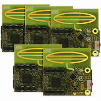
ATAVRRZ201
Description
KIT RZ201 CTLR BOARDS & SOFTWARE
Manufacturer
Atmel
Series
AVR®r
Type
802.15.4/Zigbeer
Specifications of ATAVRRZ201
Frequency
2.4GHz
Wireless Frequency
2.4 GHz
Interface Type
JTAG
Antenna
PCB Trace
Silicon Manufacturer
Atmel
Silicon Core Number
ATmega1281V, AT86RF230
Kit Application Type
Wireless Connectivity
Application Sub Type
ZigBee Wireless Network
Silicon Family Name
ZigBee
Rohs Compliant
Yes
For Use With/related Products
AT86RF230
Lead Free Status / RoHS Status
Lead free / RoHS Compliant


5183A–ZIGB–12/07/06
6.2.1
6.2.2
6-2
Programming the
Display Board
Programming the
RCB
The following steps show how to re-program the ATmega128 microcontroller located on
the Display Board.
Remove RCB from Display board.
1. Connect the 6-pin cable from the AVRISP mkII to the Display ISP connector
2. Start AVR Studio. From the Tools menu, select Program AVR, and select Con-
3. In the Program tab, select the target Device as ATmega128.
4. Ensure that the following fuse settings are selected using AVR Studio in the
5. Go back to the Program tab, in the Flash section, browse to the location of the
6. Alternatively, fuse settings can be altered using JTAG ICE mkII. In this case,
The following steps show how to re-program the ATmega1281 microcontroller located
on the RCBs.
1. Connect RCB to the Display board. Connect the 6-pin cable from the AVRISP
2. Start AVR Studio. From the Tools menu, select Program AVR, and select Con-
3. In the Program tab, select the target Device as ATmega1281.
4. Ensure that the following fuse settings are selected in the Fuses tab:
(upper right) on the Display Board. Verify that the Display Board is powered on.
nect. Choose AVRISP mkII from the list of platforms and the port where it is
connected. Press the Connect button. The AVRISP mkII programming window
should now be visible.” Note space between ‘AVR’ and ‘Studio’.
Fuses tab:
– JTAG Interface Enabled; [JTAGEN=0]
– Preserve EEPROM memory through the Chip Erase cycle; [EESAVE=0]
– Preserve EEPROM memory through chip erase cycle. [EESAVE=0]
– Boot programming section size=4096 words Boot start address=$F000;
– Brown-out detection level at VCC=2.7V; [BODLEVEL=1]
– Int. RC Osc. 8 MHz; Start-up time: 6 CK + 4ms; [CKSEL=0100 SUT=01]”.
– The final fuse value written is 0xFF, 0x91, 0xD4.
input HEX file and select the filename: rz200_display_board_v1_0.hex. Press
Program and verify that the process terminates successfully.
the Serial program downloading (SPI) enabled; [SPIEN=0] fuse must be
checked.
mkII to the RCB ISP connector (upper left) on the Display Board. Verify that the
RCB is powered on (move the switch away from the antenna).
nect. Choose AVRISP mkII from the list of platforms and the port where it is
connected. Press the Connect button. The AVRISP mkII programming window
should now be visible.
– Brown-out detection disabled; [BODLEVEL=111]
– JTAG Interface Enabled; [JTAGEN=0]
– Preserve EEPROM memory through chip erase cycle. [EESAVE=0]
– Boot program section size=4096 words Boot start address=$F000;
– Int. RC Osc. 8 MHz; Start-up time: 6 CK + 65ms; [CKSEL=0100 SUT=01]
– The final fuse value written is 0xFF, 0x91, 0xE2.
[BOOTSZ=00]; default value
[BOOTSZ=00]; default value
Demonstration Kit User Guide
Related parts for ATAVRRZ201
Image
Part Number
Description
Manufacturer
Datasheet
Request
R

Part Number:
Description:
DEV KIT FOR AVR/AVR32
Manufacturer:
Atmel
Datasheet:

Part Number:
Description:
INTERVAL AND WIPE/WASH WIPER CONTROL IC WITH DELAY
Manufacturer:
ATMEL Corporation
Datasheet:
Part Number:
Description:
Low-Voltage Voice-Switched IC for Hands-Free Operation
Manufacturer:
ATMEL Corporation
Datasheet:
Part Number:
Description:
MONOLITHIC INTEGRATED FEATUREPHONE CIRCUIT
Manufacturer:
ATMEL Corporation
Datasheet:
Part Number:
Description:
AM-FM Receiver IC U4255BM-M
Manufacturer:
ATMEL Corporation
Datasheet:
Part Number:
Description:
Monolithic Integrated Feature Phone Circuit
Manufacturer:
ATMEL Corporation
Datasheet:
Part Number:
Description:
Multistandard Video-IF and Quasi Parallel Sound Processing
Manufacturer:
ATMEL Corporation
Datasheet:
Part Number:
Description:
High-performance EE PLD
Manufacturer:
ATMEL Corporation
Datasheet:
Part Number:
Description:
8-bit Flash Microcontroller
Manufacturer:
ATMEL Corporation
Datasheet:
Part Number:
Description:
2-Wire Serial EEPROM
Manufacturer:
ATMEL Corporation
Datasheet: