ATAVRRZ201 Atmel, ATAVRRZ201 Datasheet - Page 17
ATAVRRZ201
Manufacturer Part Number
ATAVRRZ201
Description
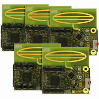
KIT RZ201 CTLR BOARDS & SOFTWARE
Manufacturer
Atmel
Series
AVR®r
Type
802.15.4/Zigbeer
Specifications of ATAVRRZ201
Frequency
2.4GHz
Wireless Frequency
2.4 GHz
Interface Type
JTAG
Antenna
PCB Trace
Silicon Manufacturer
Atmel
Silicon Core Number
ATmega1281V, AT86RF230
Kit Application Type
Wireless Connectivity
Application Sub Type
ZigBee Wireless Network
Silicon Family Name
ZigBee
Rohs Compliant
Yes
For Use With/related Products
AT86RF230
Lead Free Status / RoHS Status
Lead free / RoHS Compliant


5.2
5.3
Demonstration Kit User Guide
Reconfiguring
the network
Using the
network
All configurations of the network nodes are performed in the Configure screen on the
Display Board.
Note:
With the Configure screen displayed, the functions of the device can be changed by
using the joystick to highlight the device’s existing function. When the function is high-
lighted, pressing SW2 will cycle between the available options (Switch or LEDs).
Consult Figure 5-4 through Figure 5-7 and their captions.
The switch functions on the Display Board are shown below.
Each RCB has a Test button and three LEDs. Figure 5-9 shows an RCB with all three
LED’s illuminated:
Figure 5-9. RCB Test button
Network Monitor screen (Figure 5-8).
the Configure screen (Figure 5-7).
communicate to all devices. If any devices are out of range or become disassociated,
they will be removed from the network table.
SW1: Toggles the display between the Configure screen (Figure 5-7) and the
SW2:
Joystick: The joystick up and down switch are used to highlight the device function on
Joystick Push: By pressing down on the joystick, the PAN Coordinator will attempt to
1. When the Configure screen (Figure 5-7) is displayed, pressing this button
– LED
– Switch 1
– Switch 2
– Switch 3
This demonstration requires at least two nodes to associate with the PAN Coor-
dinator. This is because the demonstration expects a minimum of one LED
device and one switch device.
changes the highlighted function of the device. The functions are:
RCB Test button
5183A–ZIGB–12/07/06
5-3
Related parts for ATAVRRZ201
Image
Part Number
Description
Manufacturer
Datasheet
Request
R

Part Number:
Description:
DEV KIT FOR AVR/AVR32
Manufacturer:
Atmel
Datasheet:

Part Number:
Description:
INTERVAL AND WIPE/WASH WIPER CONTROL IC WITH DELAY
Manufacturer:
ATMEL Corporation
Datasheet:
Part Number:
Description:
Low-Voltage Voice-Switched IC for Hands-Free Operation
Manufacturer:
ATMEL Corporation
Datasheet:
Part Number:
Description:
MONOLITHIC INTEGRATED FEATUREPHONE CIRCUIT
Manufacturer:
ATMEL Corporation
Datasheet:
Part Number:
Description:
AM-FM Receiver IC U4255BM-M
Manufacturer:
ATMEL Corporation
Datasheet:
Part Number:
Description:
Monolithic Integrated Feature Phone Circuit
Manufacturer:
ATMEL Corporation
Datasheet:
Part Number:
Description:
Multistandard Video-IF and Quasi Parallel Sound Processing
Manufacturer:
ATMEL Corporation
Datasheet:
Part Number:
Description:
High-performance EE PLD
Manufacturer:
ATMEL Corporation
Datasheet:
Part Number:
Description:
8-bit Flash Microcontroller
Manufacturer:
ATMEL Corporation
Datasheet:
Part Number:
Description:
2-Wire Serial EEPROM
Manufacturer:
ATMEL Corporation
Datasheet: