EM250-RCM-R Ember, EM250-RCM-R Datasheet - Page 44
EM250-RCM-R
Manufacturer Part Number
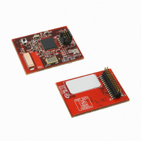
EM250-RCM-R
Description
EM250 RCM BOARD
Manufacturer
Ember
Type
Transceiver, 802.15.4/ZigBeer
Datasheet
1.EM250-RCM-R.pdf
(126 pages)
Specifications of EM250-RCM-R
Frequency
2.4GHz
For Use With/related Products
EM250
Lead Free Status / RoHS Status
Lead free / RoHS Compliant
Other names
636-1023


EM250
120-0082-000S
ther reception is dropped and the register bit
hardware generates the
til the RX FIFO is drained. Once the DMA marks a RX error, there are two conditions that will clear the error
indication: setting the appropriate
priate DMA buffer after it has unloaded.
Receiving a character always requires transmitting a character. In a case when a long stream of receive char-
acters is expected, a long sequence of (dummy) transmit characters must be generated. To avoid software or
transmit DMA initiating these transfers (and consuming unnecessary bandwidth), the SPI serializer can be in-
structed to retransmit the last transmitted character, or to transmit a busy token (
by the register bit
when the transmit FIFO is empty and the transmit serializer is idle, as indicated by a cleared
register bit in the
Every time an automatic character transmission is started, a transmit underrun is detected (as there is no data
in transmit FIFO), and the register bit
abling the automatic character transmission, the reception of new characters stops and the receive FIFO holds
characters just received.
Note: The event Receive DMA complete does not automatically mean receive FIFO empty.
Interrupts are generated on the following events:
To generate interrupts to the CPU, the interrupt masks in the
abled.
5.2.3
The SC1 I
3. The I
not implemented, so multiple master applications are not supported. The I
signals, and external pull-up resistors are required.
The SC1 I
The following signals can be made available on the GPIO pins:
The I
by a clock division ratio from the 24MHz clock:
Transmit FIFO empty and last character shifted out (0 to 1 transition of
Transmit FIFO changed from full to not full (0 to 1 transition of
Receive FIFO changed from empty to not empty (0 to 1 transition of
Transmit DMA buffer A/B complete (1 to 0 transition of
Receive DMA buffer A/B complete (1 to 0 transition of
Received and lost character while receive FIFO was full (Receive overrun error)
Transmitted character while transmit FIFO was empty (Transmit underrun error)
Programmable clock frequency (400kHz max.)
Supports both 7-bit and 10-bit addressing
MSDA (serial data)
MSCL (serial clock)
Nominal Rate = 24MHz / ( 2 * (LIN + 1) * 2
2
C Master controller obtains its reference clock from a programmable clock generator. Clock rates are set
2
I
C Master controller supports Standard (100kbps) and Fast (400kbps) I
2
2
2
C Master Mode
C controller is only available in master mode. The SC1 I
C mode has the following features:
SC1_SPISTAT
SC_SPIRPT
INT_SCRXOVF
in the
register.
SC_TX/RXDMARST
SC1_SPICFG
INT_SCTXUND
interrupt, but the DMA register will not indicate the error condition un-
Page 44
EXP
SC_SPIRXOVF
)
register. This functionality can only be enabled (or disabled)
in the
bit in the
SC_RXACTA/B
INT_SC1FLAG
SC_TXACTA/B
in the
INT_SC1CFG
SC1_DMACTRL
2
C controller is enabled with
SC1_SPISTAT
SC_SPITXFREE
)
SC_SPIRXVAL
)
register is set. Note that after dis-
2
and
C signals are pure open-collector
SC_SPITXIDLE
2
C modes. Address arbitration is
register, or loading the appro-
INT_CFG
register is set. The RX FIFO
0xFF
)
)
), which is determined
registers must be en-
)
SC_SPITXIDLE
SC1_MODE
set to
Related parts for EM250-RCM-R
Image
Part Number
Description
Manufacturer
Datasheet
Request
R

Part Number:
Description:
EM250 BREAKOUT BOARD
Manufacturer:
Ember
Datasheet:

Part Number:
Description:
KIT JUMP START FOR EM250
Manufacturer:
Ember
Datasheet:

Part Number:
Description:
KIT EVAL EM250 RF TEST
Manufacturer:
Ember
Datasheet:

Part Number:
Description:
IC ZIGBEE SYSTEM-ON-CHIP 48-QFN
Manufacturer:
Ember
Datasheet:

Part Number:
Description:
KIT DEV FOR EM250
Manufacturer:
Ember
Datasheet:

Part Number:
Description:
KIT DEV EMBER ZIGBEE W/PCWH
Manufacturer:
Custom Computer Services Inc (CCS)

Part Number:
Description:
PROGRAMMER USB FLASH EM250/260
Manufacturer:
Ember
Datasheet:

Part Number:
Description:
IC ZIGBEE SYSTEM-ON-CHIP 40-QFN
Manufacturer:
Ember
Datasheet:
Part Number:
Description:
IC RF TXRX ZIGBEE 128KB 48QFN
Manufacturer:
Ember
Datasheet:
Part Number:
Description:
IC RF TXRX ZIGBEE 192KB 48QFN
Manufacturer:
Ember
Datasheet:

Part Number:
Description:
INSIGHT ADAPTER FOR EM2XX
Manufacturer:
Ember
Datasheet:

Part Number:
Description:
IAR EWARM LICENCE FOR EM35X
Manufacturer:
Ember
Datasheet:

Part Number:
Description:
INSIGHT ADAPTER 3 FOR EM35X
Manufacturer:
Ember
Datasheet:

Part Number:
Description:
EM35X BREAKOUT BOARD
Manufacturer:
Ember
Datasheet:

Part Number:
Description:
EM260 RCM BOARD
Manufacturer:
Ember
Datasheet: