TWR-MCF51MM Freescale Semiconductor, TWR-MCF51MM Datasheet - Page 8
TWR-MCF51MM
Manufacturer Part Number
TWR-MCF51MM
Description
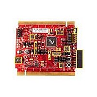
TOWER SYSTEM BOARD MCF51MM
Manufacturer
Freescale Semiconductor
Series
ColdFire®, Flexis™r
Type
MCUr
Specifications of TWR-MCF51MM
Contents
Board, 3 Modules, MED-EKG Kit, Cables, Documentation, DVD
Product
Microcontroller Modules
Data Bus Width
32 bit
Core Processor
MCF51MM
Clock Speed
32 KHz
Interface Type
RS232, RS485, CAN , USB
Flash
256 KB
Operating Supply Voltage
3.3 V
Silicon Manufacturer
Freescale
Core Architecture
Coldfire
Core Sub-architecture
Coldfire V1
Silicon Core Number
MCF51
Silicon Family Name
Flexis - MCF51MM
Rohs Compliant
Yes
For Use With/related Products
Freescale Tower System, MCF51MM
Lead Free Status / RoHS Status
Lead free / RoHS Compliant


The assembled Tower System now has
three USB connectors:
1. The USB connector on TWR-SER
2. The USB connector on TWR-
3. The USB connector on the Primary
To power on an assembled Tower
System, connect the PC to mini-USB
port (J14) on the TWR-SER module. The
MCF51MM256 is programmed with a
blinking LED application, so you should
see LED 1 to LED 3 blink the first time
the board is powered. LED 1 to LED 3 are
located near the potentiometer. When set
up as an assembled Tower System, the
power source is from the TWR-SER mini-
TOWER SYSTEM
STEP
connects to the USB peripheral of the
MCF51MM256 MCU.
MCF51MM is used for programming
and debugging the MCF51MM256
MCU. The debugger interface is the
Freescale open-source background
debug module (OSBDM).
elevator merely powers the Tower
System. There is no data through this
connector and is not used in this kit.
3
Connect the Tower
System to the Computer
USB. The TWR-MCF51MM mini-USB acts
only as an OSBDM function and should
not be used to power the system. Be sure
to connect TWR-SER USB before the
TWR-MCF51MM USB. Do not connect
TWR-MCF51MM USB without TWR-SER
USB or damage could be caused.
NOTE: When the TWR-MCF51MM module is used stand-alone,
USB port (J17) is both the power source and the debugger
interface. When the TWR-MCF51MM module is assembled as a
Tower System, the USB port (J17) is only a OSBDM.
LEDs 1 to 4 correspond to silk-screened labels D9 to D12 on
the TWR-MCF51MM module.
Related parts for TWR-MCF51MM
Image
Part Number
Description
Manufacturer
Datasheet
Request
R

Part Number:
Description:
Power Management IC Development Tools Low-volt 3-phase MC
Manufacturer:
Freescale Semiconductor
Datasheet:
Part Number:
Description:
K53N512CMD100 TWR Module
Manufacturer:
Freescale Semiconductor
Datasheet:
Part Number:
Description:
TWR-K53N512 Dev Kit
Manufacturer:
Freescale Semiconductor
Datasheet:

Part Number:
Description:
CONV DC/DC TRI OUT 5,15,-15V
Manufacturer:
Murata Power Solutions Inc
Datasheet:

Part Number:
Description:
CONV DC/DC TRI OUT 5,12,-12V
Manufacturer:
Murata Power Solutions Inc
Datasheet:

Part Number:
Description:
CONV DC/DC TRI OUT 5,15,-15V
Manufacturer:
Murata Power Solutions Inc
Datasheet:

Part Number:
Description:
LCD MODULE FOR TWR SYSTEM
Manufacturer:
Freescale Semiconductor
Datasheet:

Part Number:
Description:
DC/DC TH 11W 5-5/12V Triple A
Manufacturer:
Murata Power Solutions Inc
Datasheet:


Part Number:
Description:
TOWER SYSTEM PROTO
Manufacturer:
Freescale Semiconductor
Datasheet:

Part Number:
Description:
TOWER ELEVATOR BOARDS HARDWARE
Manufacturer:
Freescale Semiconductor
Datasheet:

Part Number:
Description:
TOWER SERIAL I/O HARDWARE
Manufacturer:
Freescale Semiconductor
Datasheet:

Part Number:
Description:
TOWER SYSTEM BOARD MPC5125
Manufacturer:
Freescale Semiconductor
Datasheet: