EVAL-ADM1066LFEBZ Analog Devices Inc, EVAL-ADM1066LFEBZ Datasheet - Page 20
EVAL-ADM1066LFEBZ
Manufacturer Part Number
EVAL-ADM1066LFEBZ
Description
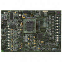
BOARD EVALUATION FOR ADM1066LF
Manufacturer
Analog Devices Inc
Specifications of EVAL-ADM1066LFEBZ
Main Purpose
Power Management, Power Supply Supervisor/Tracker/Sequencer
Embedded
No
Utilized Ic / Part
ADM1066
Primary Attributes
10 Channel Supervisor / Sequencer, 6 Voltage Output DACs
Secondary Attributes
GUI Programmable via SMBus (via USB)
Lead Free Status / RoHS Status
Lead free / RoHS Compliant


ADM1066
Monitoring Fault Detector
The monitoring fault detector block is used to detect a failure
on an input. The logical function implementing this is a wide
OR gate that can detect when an input deviates from its expected
condition. The clearest demonstration of the use of this block
is in the PWRGD state, where the monitor block indicates that
a failure on one or more of the VP1,VP2, or VP3 inputs has
occurred.
No programmable delay is available in this block because the
triggering of a fault condition is likely to be caused by a supply
falling out of tolerance. In this situation, the device must react
as quickly as possible. Some latency occurs when moving out of
this state because it takes a finite amount of time (~20 μs) for the
state configuration to download from the EEPROM into the SE.
Figure 29 is a block diagram of the monitoring fault detector.
VP1
VX5
LOGIC INPUT CHANGE
OR FAULT DETECTION
Figure 29. Monitoring Fault Detector Block Diagram
SUPPLY FAULT
DETECTION
WARNINGS
MONITORING FAULT
DETECTOR
1-BIT FAULT
DETECTOR
1-BIT FAULT
DETECTOR
1-BIT FAULT
DETECTOR
MASK
SENSE
MASK
SENSE
MASK
FAULT
FAULT
FAULT
Rev. D | Page 20 of 32
Timeout Detector
The timeout detector allows the user to trap a failure to ensure
proper progress through a power-up or power-down sequence.
In the sample application shown in Figure 28, the timeout next-
state transition is from the EN3V3 and EN2V5 states. For the
EN3V3 state, the signal 3V3ON is asserted on the PDO1 output
pin upon entry to this state to turn on a 3.3 V supply.
This supply rail is connected to the VP2 pin, and the sequence
detector looks for the VP2 pin to go above its undervoltage
threshold, which is set in the supply fault detector (SFD)
attached to that pin.
The power-up sequence progresses when this change is
detected. If, however, the supply fails (perhaps due to a short
circuit overloading this supply), the timeout block traps the
problem. In this example, if the 3.3 V supply fails within 10 ms,
the SE moves to the DIS3V3 state and turns off this supply by
bringing PDO1 low. It also indicates that a fault has occurred by
taking PDO3 high. Timeout delays of 100 μs to 400 ms can be
programmed.
FAULT AND STATUS REPORTING
The ADM1066 has a fault latch for recording faults. Two registers,
FSTAT1 and FSTAT2, are set aside for this purpose. A single bit
is assigned to each input of the device, and a fault on that input
sets the relevant bit. The contents of the fault register can be
read out over the SMBus to determine which input(s) faulted.
The fault register can be enabled or disabled in each state. To
latch data from one state, ensure that the fault latch is disabled
in the following state. This ensures that only real faults are
captured and not, for example, undervoltage conditions that
may be present during a power-up or power-down sequence.
The ADM1066 also has a number of status registers. These include
more detailed information, such as whether an undervoltage or
overvoltage fault is present on a particular input. The status
registers also include information on ADC limit faults. Note
that the data in the status registers is not latched in any way and,
therefore, is subject to change at any time.
See the AN-698 Application Note at
details about the ADM1066 registers.
www.analog.com
for full
Related parts for EVAL-ADM1066LFEBZ
Image
Part Number
Description
Manufacturer
Datasheet
Request
R

Part Number:
Description:
IC, ADJ LDO REG, 1.5V TO 5V 250mA MSOP-8
Manufacturer:
Vishay
Datasheet:

Part Number:
Description:
IC, ADJ LDO REG, 1.5V TO 5V 0.6A 8-TSSOP
Manufacturer:
Vishay
Datasheet:
Part Number:
Description:
IC, ADJ LDO REG, 1.5V TO 5V 250mA MSOP-8
Manufacturer:
Vishay
Datasheet:

Part Number:
Description:
IC ADJ LDO REG 1.5V TO 5V 150mA 5-SOT-23
Manufacturer:
Vishay
Datasheet:

Part Number:
Description:
BOARD EVAL AS1324-AD
Manufacturer:
austriamicrosystems
Datasheet:
Part Number:
Description:
IC, ADJ LDO REG, 1.5V TO 5V 0.6A 8-TSSOP
Manufacturer:
Vishay
Datasheet:

Part Number:
Description:
IC, ADJ LDO REG, 1.5V TO 5V, 0.3A, MSOP8
Manufacturer:
Vishay
Datasheet:
Part Number:
Description:
IC, ADJ LDO REG, 1.5V TO 5V, 0.3A, MSOP8
Manufacturer:
Vishay
Datasheet:
Part Number:
Description:
IC, ADJ LDO REG 1.215V TO 5V 0.3A MSOP-8
Manufacturer:
Vishay
Datasheet:
Part Number:
Description:
IC, ADJ LDO REG 1.215V TO 5V 0.3A MSOP-8
Manufacturer:
Vishay
Datasheet:

Part Number:
Description:
±1.7g Dual-Axis IMEMS Accelerometer Evaluation Board
Manufacturer:
Analog Devices Inc
Datasheet:

Part Number:
Description:
IC MULTIPLIER ANALOG 8-SOIC T/R
Manufacturer:
Analog Devices Inc
Datasheet:

Part Number:
Description:
IC ANALOG MULTIPLIER 8-DIP
Manufacturer:
Analog Devices Inc
Datasheet:
Part Number:
Description:
IC ANALOG MULTIPLIER 8-SOIC
Manufacturer:
Analog Devices Inc
Datasheet:
Part Number:
Description:
IC ANALOG MULTIPLIER 8-DIP
Manufacturer:
Analog Devices Inc
Datasheet: