STEVAL-IPE010V1 STMicroelectronics, STEVAL-IPE010V1 Datasheet - Page 63
STEVAL-IPE010V1
Manufacturer Part Number
STEVAL-IPE010V1
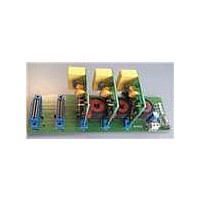
Description
KIT DEMO ENERGY METER STPMC1/S1
Manufacturer
STMicroelectronics
Type
Other Power Managementr
Specifications of STEVAL-IPE010V1
Main Purpose
Power Management, Energy/Power Meter
Embedded
No
Utilized Ic / Part
STPMC1, STPMS1
Maximum Operating Temperature
+ 85 C
Product
Power Management Development Tools
Lead Free Status / RoHS Status
Lead free / RoHS Compliant
Secondary Attributes
-
Primary Attributes
-
Lead Free Status / Rohs Status
Lead free / RoHS Compliant
For Use With/related Products
STPMC1, STPMS1
Other names
497-10754


STPMC1
Figure 23. Data records reconstruction
9.21.3
The first read out byte of the data record is the least significant byte (LSB) of the data value
and of course, the fourth byte is the most significant byte (MSB) of the data value. Each byte
can be further divided into a pair of 4-bit nibbles, most and least significant nibble (msn, lsn).
This division makes sense with the MSB of the data value because the msn holds the parity
code.
The sequence of the data record during the reading operation is fixed. However, an
application may apply a precharge command (see mode signal description) prior to the
reading phase. This command increases the group pointer forcing the device to respond
with the next group data records sequence.
The system that reads the data record from the STPMC1 should check the integrity of each
data record, as indicated in paragraph
repeated, but this time only the shifting should be applied; otherwise new data would be
latched into transmission latches, thus losing the previous reading.
Normally, each byte is read out as the most significant bit (msb) first. But this can be
changed by setting the MSBF configuration bit in the STPMC1 CFL data record. If this is
done, each byte is read out as the least significant bit (lsb) first.
Writing procedure
Each writable bit (configuration and mode bits) has its own 7-bit absolute address. For the
configuration bits, the 7-bit address value corresponds to its decimal value, while for the
mode bits the addresses are those indicated in the mode signal paragraph.
In order to change the state of a latch one must send to the STPMC1 a byte of data which is
the normal way to send data via SPI. This byte consists of 1-bit data to be latched (msb),
followed by 7-bit address of destination latch, which makes total 8 bits of command byte, as
summarized in the table below.
Doc ID 15728 Rev 4
9.17.8
. If the check fails, the reading should be
Theory of operation
63/77
Related parts for STEVAL-IPE010V1
Image
Part Number
Description
Manufacturer
Datasheet
Request
R

Part Number:
Description:
BOARD DEMO TFT DISPLAY STR91
Manufacturer:
STMicroelectronics
Datasheet:

Part Number:
Description:
BOARD EVAL FOR MEMS SENSORS
Manufacturer:
STMicroelectronics
Datasheet:

Part Number:
Description:
KIT DEV STARTER ST10F276Z5
Manufacturer:
STMicroelectronics
Datasheet:

Part Number:
Description:
BOARD EVAL HDMI $ VIDEO SWITCH
Manufacturer:
STMicroelectronics
Datasheet:

Part Number:
Description:
BOARD DEMO ACCELEROMETER DIL24
Manufacturer:
STMicroelectronics
Datasheet:

Part Number:
Description:
BOARD STLM75/STDS75/ST72F651
Manufacturer:
STMicroelectronics
Datasheet:

Part Number:
Description:
EVAL BOARD 3AXIS MEMS ACCELLRMTR
Manufacturer:
STMicroelectronics
Datasheet:

Part Number:
Description:
BOARD EVAL 8BIT MICRO + TDE1708
Manufacturer:
STMicroelectronics
Datasheet:

Part Number:
Description:
EVAL BOARD A/D TS4657
Manufacturer:
STMicroelectronics
Datasheet:

Part Number:
Description:
BOARD ADAPTER 20DIP LIS3LV02DL
Manufacturer:
STMicroelectronics
Datasheet:
Part Number:
Description:
STMicroelectronics [RIPPLE-CARRY BINARY COUNTER/DIVIDERS]
Manufacturer:
STMicroelectronics
Datasheet:
Part Number:
Description:
STMicroelectronics [LIQUID-CRYSTAL DISPLAY DRIVERS]
Manufacturer:
STMicroelectronics
Datasheet:
Part Number:
Description:
BOARD EVAL FOR MEMS SENSORS
Manufacturer:
STMicroelectronics
Datasheet: