STEVAL-IPE010V1 STMicroelectronics, STEVAL-IPE010V1 Datasheet - Page 25
STEVAL-IPE010V1
Manufacturer Part Number
STEVAL-IPE010V1
Description
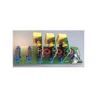
KIT DEMO ENERGY METER STPMC1/S1
Manufacturer
STMicroelectronics
Type
Other Power Managementr
Specifications of STEVAL-IPE010V1
Main Purpose
Power Management, Energy/Power Meter
Embedded
No
Utilized Ic / Part
STPMC1, STPMS1
Maximum Operating Temperature
+ 85 C
Product
Power Management Development Tools
Lead Free Status / RoHS Status
Lead free / RoHS Compliant
Secondary Attributes
-
Primary Attributes
-
Lead Free Status / Rohs Status
Lead free / RoHS Compliant
For Use With/related Products
STPMC1, STPMS1
Other names
497-10754


STPMC1
Figure 10. LIN and BFR behavior when f
9.7
The in-band base frequency resets the flag BFR. If BFR is cleared, the measured period
value is latched, otherwise a default value of period is used as a stable data to compute
frequency needed to adapt the decimation filter and to perform frequency compensation of
reactive energy and RMS current I
The BFR flag is also set if the register value of the RMS is too low. In this case also the
status bit LOW is set.
The condition for setting LOW and consequently BFR of each phase is U
(U
the register value goes above 256 (U
the presence of the line voltage.
When the BFR error is set, the computation of power is zero and the energy registers
(active, reactive and fundamental) are blocked, unless single wire mode operation is entered
(see
When the MOP, MON and LED pins are configured to provide the pulsed energy information
they are held low if BFR is set.
The 3-ph status bit BFF is the OR of each phase bit BFR.
Single wire operation mode: SWM (status bits: NAH, BFR,
configuration bit FRS)
The STPMC1 supports single wire meter (SWM) operation. In this condition, since there is
no voltage information, the current RMS values, instead of the energies, are accumulated in
20-bit dedicated registers located in ACR, ACS, ACT (20-bit accumulator of RMS I
[Ah]).
Each ACx register contains a 20-bit accumulator of the relative phase current I
8-bit register carrying the information about phase delay between voltage channels.
Xmax
Section
= 2
12
) it means if the U
9.7).
Doc ID 15728 Rev 4
X
line
register drops below 128 LOW and BFR are cleared when
X
> f
in case of non Rogowski current sensor.
X
MCLK
> U
Xmax
/2
16
/16). BFR, then, gives also information about
Theory of operation
X
< U
X
Xmax
[Ah] and an
X
per hour
/32
25/77
Related parts for STEVAL-IPE010V1
Image
Part Number
Description
Manufacturer
Datasheet
Request
R

Part Number:
Description:
BOARD DEMO TFT DISPLAY STR91
Manufacturer:
STMicroelectronics
Datasheet:

Part Number:
Description:
BOARD EVAL FOR MEMS SENSORS
Manufacturer:
STMicroelectronics
Datasheet:

Part Number:
Description:
KIT DEV STARTER ST10F276Z5
Manufacturer:
STMicroelectronics
Datasheet:

Part Number:
Description:
BOARD EVAL HDMI $ VIDEO SWITCH
Manufacturer:
STMicroelectronics
Datasheet:

Part Number:
Description:
BOARD DEMO ACCELEROMETER DIL24
Manufacturer:
STMicroelectronics
Datasheet:

Part Number:
Description:
BOARD STLM75/STDS75/ST72F651
Manufacturer:
STMicroelectronics
Datasheet:

Part Number:
Description:
EVAL BOARD 3AXIS MEMS ACCELLRMTR
Manufacturer:
STMicroelectronics
Datasheet:

Part Number:
Description:
BOARD EVAL 8BIT MICRO + TDE1708
Manufacturer:
STMicroelectronics
Datasheet:

Part Number:
Description:
EVAL BOARD A/D TS4657
Manufacturer:
STMicroelectronics
Datasheet:

Part Number:
Description:
BOARD ADAPTER 20DIP LIS3LV02DL
Manufacturer:
STMicroelectronics
Datasheet:
Part Number:
Description:
STMicroelectronics [RIPPLE-CARRY BINARY COUNTER/DIVIDERS]
Manufacturer:
STMicroelectronics
Datasheet:
Part Number:
Description:
STMicroelectronics [LIQUID-CRYSTAL DISPLAY DRIVERS]
Manufacturer:
STMicroelectronics
Datasheet:
Part Number:
Description:
BOARD EVAL FOR MEMS SENSORS
Manufacturer:
STMicroelectronics
Datasheet: