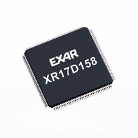
XR17D154IV-F Exar Corporation, XR17D154IV-F Datasheet - Page 49

XR17D154IV-F
Manufacturer Part Number
XR17D154IV-F
Description
IC UART PCI BUS QUAD 144LQFP
Manufacturer
Exar Corporation
Type
IrDA or RS- 485r
Datasheet
1.XR17D154CV-F.pdf
(69 pages)
Specifications of XR17D154IV-F
Number Of Channels
4, QUART
Package / Case
144-LQFP
Features
*
Fifo's
64 Byte
Protocol
RS485
Voltage - Supply
3.3V, 5V
With Auto Flow Control
Yes
With Irda Encoder/decoder
Yes
With False Start Bit Detection
Yes
With Modem Control
Yes
Mounting Type
Surface Mount
Data Rate
6.25 Mbps
Supply Voltage (max)
5.5 V
Supply Voltage (min)
3 V
Supply Current
4 mA
Maximum Operating Temperature
+ 85 C
Minimum Operating Temperature
- 40 C
Mounting Style
SMD/SMT
Operating Supply Voltage
3.3 V or 5 V
No. Of Channels
4
Uart Features
Tx/Rx FIFO Counters
Supply Voltage Range
3V To 5.5V
Operating Temperature Range
-40°C To +85°C
Digital Ic Case Style
LQFP
Rohs Compliant
Yes
Lead Free Status / RoHS Status
Lead free / RoHS Compliant
Lead Free Status / RoHS Status
Lead free / RoHS Compliant, Lead free / RoHS Compliant
Other names
1016-1290
Available stocks
Company
Part Number
Manufacturer
Quantity
Price
Company:
Part Number:
XR17D154IV-F
Manufacturer:
ADI
Quantity:
1 046
Company:
Part Number:
XR17D154IV-F
Manufacturer:
Exar Corporation
Quantity:
10 000
xr
REV. 1.2.2
EFR[4]: Enhanced Function Bits Enable
Enhanced function control bit. This bit enables the functions in IER bits 4-7, ISR bits 4-5, FCR bits 4-5, and
MCR bits 5-7 to be modified. After modifying any enhanced bits, EFR bit-4 can be set to a logic 0 to latch the
new values. This feature prevents legacy software from altering or overwriting the enhanced functions once
set. Normally, it is recommended to leave it enabled, logic 1.
•
•
EFR[5]: Special Character Detect Enable
•
•
Logic 0 = modification disable/latch enhanced features. IER bits 4-7, ISR bits 4-5, FCR bits 4-5, and MCR
bits 5-7 are saved to retain the user settings. After a reset, the IER bits 4-7, ISR bits 4-5, FCR bits 4-5, and
MCR bits 5-7 are set to a logic 0 to be compatible with the industry standard 16550 (default).
Logic 1 = Enables the enhanced functions. When this bit is set to a logic 1 all enhanced features are
enabled.
Logic 0 = Special Character Detect Disabled (default).
Logic 1 = Special Character Detect Enabled. The UART compares each incoming receive character with
data in Xoff-2 register. If a match exists, the received data will be transferred to FIFO and ISR bit-4 will be set
to indicate detection of the special character. Bit-0 corresponds with the LSB bit for the receive character. If
flow control is set for comparing Xon1, Xoff1 (EFR [1:0]=’10’) then flow control and special character work
normally. However, if flow control is set for comparing Xon2, Xoff2 (EFR[1:0]=’01’) then flow control works
normally, but Xoff2 will not go to the FIFO, and will generate an Xoff interrupt and a special character
interrupt.
EFR
TX S/W FLOW CONTROL
C
ONT
X
X
X
0
0
1
1
0
1
0
1
BIT
-3
-3
EFR
C
ONT
X
X
X
0
1
0
1
1
0
0
1
BIT
-2
-2
T
ABLE
RX S/W FLOW CONTROL
EFR
C
ONT
19: S
X
X
X
X
0
0
1
1
1
1
1
BIT
-1
-1
OFTWARE
EFR
C
ONT
X
X
X
X
0
1
0
1
1
1
1
F
BIT
49
LOW
-0
-0
UNIVERSAL (3.3V AND 5V) PCI BUS QUAD UART
C
No transmit flow control
Transmit Xon2, Xoff2
Transmit Xon1, Xoff1
Transmit Xon1 and Xon2, Xoff1 and Xoff2
No receive flow control
Receiver compares Xon2, Xoff2
Receiver compares Xon1, Xoff1
Transmit Xon2, Xoff2
Receiver compares Xon1 or Xon2, Xoff1 or Xoff2
Transmit Xon1, Xoff1
Receiver compares Xon1 or Xon2, Xoff1 or Xoff2
No transmit flow control
Receiver compares Xon1 and Xon2, Xoff1 and Xoff2
Transmit Xon1 and Xon2, Xoff1 and Xoff2
Receiver compares Xon1 and Xon2, Xoff1 and Xoff2
ONTROL
S
F
OFTWARE
UNCTIONS
F
LOW
C
ONTROL
F
UNCTIONS
XR17D154


