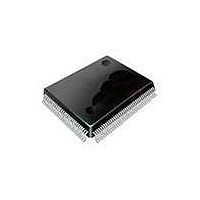
SP508CF-L Exar Corporation, SP508CF-L Datasheet - Page 4

SP508CF-L
Manufacturer Part Number
SP508CF-L
Description
IC TXRX MULTIPROTOCOL 100LQFP
Manufacturer
Exar Corporation
Type
Transceiverr
Datasheet
1.SP508CF-L.pdf
(29 pages)
Specifications of SP508CF-L
Package / Case
100-LQFP
Number Of Drivers/receivers
8/8
Protocol
Multiprotocol
Voltage - Supply
5V
Mounting Type
Surface Mount
Input Voltage Range (max)
7 V
Maximum Operating Temperature
+ 70 C
Maximum Power Dissipation
1.52 W
Minimum Operating Temperature
0 C
Mounting Style
SMD/SMT
Number Of Drivers
8
Operating Supply Voltage
5 V
Propagation Delay Time
1 us
Supply Current (max)
100 mA
Lead Free Status / RoHS Status
Lead free / RoHS Compliant
Lead Free Status / RoHS Status
Lead free / RoHS Compliant, Lead free / RoHS Compliant
Other names
1016-1192
Available stocks
Company
Part Number
Manufacturer
Quantity
Price
Company:
Part Number:
SP508CF-L
Manufacturer:
Exar Corporation
Quantity:
135
Company:
Part Number:
SP508CF-L
Manufacturer:
Exar
Quantity:
80
Part Number:
SP508CF-L
Manufacturer:
SIPEX
Quantity:
20 000
T
of -40°C to =+85°C, unless otherwise specified.
A
= 0°C to +70°C and V
PARAMETER
V.11 RECEIVER (cont)
DC Parameters (cont.)
Input Current
Current w/ 100Ω Termination
Input Impedance
AC Parameters
Propagation Delay
t
t
Skew(|t
Max.Transmission Rate
Channel to Channel Skew
V.35 DRIVER
DC Parameters
Outputs
AC Parameters
Outputs
V.35 RECEIVER
DC Parameters
Inputs
AC Parameters
Propagation Delay
t
t
Skew(|t
Max.Transmission Rate
Channel to Channel Skew
TRANSCEIVER LEAkAgE CURRENT
Driver Output 3-State Current
Rcvr Output 3-State Current
POWER REQUIREMENTS
V
I
(V.28/RS-232)
(V./RS-422)
(EIA-530 & RS-449)
(V.35)
(EIA-530A)
CC
CC
(Shutdown Mode)
Exar Corporation 48720 Kato Road, Fremont CA, 94538 • 50-668-707 • www.exar.com SP508_00_02709
Test Terminated Voltage
Offset
Output Overshoot
Source Impedance
Short-Circuit Impedance
Transition Time
Propagation Delay
t
t
Differential Skew
(|t
Max.Transmission Rate
Channel to Channel Skew
Sensitivity
Source Impedance
Short-Circuit Impedance
PHL
PLH
PHL
PLH
PHL
PLH
phl
-t
phl
phl
plh
-t
-t
plh
|)
plh
|)
|)
CC
= +4.75V to +5.25V unless otherwise noted. The ♦ denotes the specifications which applies to full temperature range
-0.2V
MIN.
–3.25
±0.44
4.75
135
135
20
50
20
90
20
4
ST
TYP.
5.00
±50
500
230
270
70
200
30
30
30
30
30
30
95
5
2
7
5
5
5
2
+0.2V
±60.75
MAX. UNITS
±3.25
±0.66
+200
±0.6
5.25
150
165
165
110
85
85
0
20
85
85
0
85
85
0
0
4
ST
Mbps
Mbps
Mbps
Volts
Volts
Volts
Volts
mA
mA
mV
mA
mA
mA
mA
mA
kΩ
µA
µA
µA
ns
ns
ns
ns
ns
ns
ns
ns
ns
ns
ns
ns
ns
Ω
Ω
Ω
Ω
ELECTRICAL SPECIFICATIONS
♦
♦
♦
♦
♦
♦
♦
♦
♦
♦
♦
♦
♦
♦
♦
♦
♦
♦
♦
♦
♦
♦
♦
CONDITIONS
per Figure 20 and 22;
power on or off
per Figure 23 and 24
V
Using C
per Figures 33 and 38
per Figures 33 and 38
per Figure 33
per Figure 25
per Figure 25
per Figure 25; V
per Figure 27; Z
per Figure 28
V
per Figure 29; 0% to 90%
per Figure 33 and 36; C
per Figure 33 and 36; C
per Figure 33 and 36; C
per Figure 30; Z
per Figure 3
V
per Figure 33 and 38; C
per Figure 33 and 38; C
per Figure 33; C
per Figure 32; Drivers disabled
T
All I
f
f
f
V.35 @ f
f
IN
IN
IN
IN
X
CC
CC
CC
= 20kbps; Drivers active & loaded
= 0Mbps; Drivers active & loaded
= 0Mbps; Drivers active & loade
= 0Mbps; Drivers active & loaded
& R
CC
= +5V for AC parameters
= +5V for AC parameters
= +5V for AC parameters
values are with V
X
disabled, 0.4V - V
L
IN
= 50pF;
= 0Mbps, V.28 @ 20kbps
S
S
ST = Steady state value
L
= V
= V
= 20pF
2
2
/V
/V
CC
L
L
L
L
L
x 50
= 20pF
= 20pF
= 20pF
= 20pF
= 20pF
x 50Ω
= +5V
O
- 2.4V


