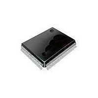
SP508CF-L Exar Corporation, SP508CF-L Datasheet - Page 2

SP508CF-L
Manufacturer Part Number
SP508CF-L
Description
IC TXRX MULTIPROTOCOL 100LQFP
Manufacturer
Exar Corporation
Type
Transceiverr
Datasheet
1.SP508CF-L.pdf
(29 pages)
Specifications of SP508CF-L
Package / Case
100-LQFP
Number Of Drivers/receivers
8/8
Protocol
Multiprotocol
Voltage - Supply
5V
Mounting Type
Surface Mount
Input Voltage Range (max)
7 V
Maximum Operating Temperature
+ 70 C
Maximum Power Dissipation
1.52 W
Minimum Operating Temperature
0 C
Mounting Style
SMD/SMT
Number Of Drivers
8
Operating Supply Voltage
5 V
Propagation Delay Time
1 us
Supply Current (max)
100 mA
Lead Free Status / RoHS Status
Lead free / RoHS Compliant
Lead Free Status / RoHS Status
Lead free / RoHS Compliant, Lead free / RoHS Compliant
Other names
1016-1192
Available stocks
Company
Part Number
Manufacturer
Quantity
Price
Company:
Part Number:
SP508CF-L
Manufacturer:
Exar Corporation
Quantity:
135
Company:
Part Number:
SP508CF-L
Manufacturer:
Exar
Quantity:
80
Part Number:
SP508CF-L
Manufacturer:
SIPEX
Quantity:
20 000
ABSOLUTE MAXIMUM RATINGS
These are stress ratings only and functional operation of the
device at these ratings or any other above those indicated in
the operation sections of the specifications below is not implied.
Exposure to absolute maximum rating conditions for extended
periods of time may affect reliability.
V
Input Voltages:
Output Voltages:
Storage Temperature . .................................................-65°C to +50°C
Power Dissipation . ..................................................................520mW
(derate 9.0mW/°C above +70°C)
Package Derating:
T
ture range of -40°C to =+85°C, unless otherwise specified.
A
CC
= 0°C to +70°C and V
.................................................................................................+7V
PARAMETER
LOGIC INPUTS
LOGIC OUTPUTS
V.28 DRIVER
DC Parameters
Outputs
AC Parameters
Outputs
V.28 RECEIVER
DC Parameters
Inputs
AC Parameters
Propagation Delay
Exar Corporation 48720 Kato Road, Fremont CA, 94538 • 50-668-707 • www.exar.com SP508_00_02709
V
V
V
V
Open Circuit Voltage
Loaded Voltage
Short-Circuit Current
Power-Off Impedance
Transition Time
Instantaneous Slew Rate
Propagation Delay
t
t
Max.Transmission Rate
Input Impedance
Open-Circuit Bias
HIGH Threshold
LOW Threshold
t
t
PHL
PLH
PHL
PLH
IL
IH
OL
OH
Logic ................................................ -0.3V to (V
Drivers . ............................................. -0.3V to (V
Receivers .............................................................±5.5V
Logic ................................................ -0.3V to (V
Drivers . ....................................................................±2V
Receivers ......................................... -0.3V to (V
ø
ø
JA
JC
...................................................................52.7 °C/W
.....................................................................6.5 °C/W
CC
= +4.75V to +5.25V unless otherwise noted. The ♦ denotes the specifications which applies to full tempera-
MIN.
±5.0
300
20
2.0
0.5
0.5
0.8
50
50
3
TYP.
CC
CC
CC
CC
230
00
00
2.4
.7
.2
+0.5V)
+0.5V)
+0.5V)
+0.5V)
MAX. UNITS
±00
+2.0
±5
±5
500
500
0.8
0.4
.5
3.0
30
2
5
5
7
STORAGE CONSIDERATIONS
Due to the relatively large package size, storage in a low
humidity environment is preferred. Large high density plastic
packages are moisture sensitive and should be stored in Dry
Vapor Barrier Bags. Prior to usage, the parts should remain
bagged and stored below 40°C and 60%RH. If the parts are
removed from the bag, they should be used within 48 hours
or stored in an environment at or below 20%RH. If the above
conditions cannot be followed, the parts should be baked
for four hours at 25°C in order to remove moisture prior to
soldering. Exar ships the 00-pin LQFP in Dry Vapor Barrier
Bags with a humidity indicator card and desiccant pack. The
humidity indicator should be below 30%RH.
Volts
Volts
Volts
Volts
Volts
Volts
Volts
Volts
Volts
V/µs
kbps
mA
kΩ
µs
µs
µs
ns
ns
Ω
♦
♦
♦
♦
♦
♦
♦
♦
♦
♦
♦
♦
♦
♦
♦
♦
♦
♦
CONDITIONS
ELECTRICAL SPECIFICATIONS
I
I
per Figure
per Figure 2
per Figure 4, V
per Figure 5
V
per Figure 6; +3V to -3V
per Figure 3
per Figure 7
per Figure 8
V
OUT
OUT
CC
CC
= –3.2mA
= .0mA
= +5V for AC parameters
= +5V for AC parameters
OUT
=0V


