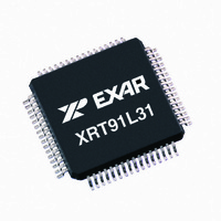
XRT91L31IQ-F Exar Corporation, XRT91L31IQ-F Datasheet - Page 9

XRT91L31IQ-F
Manufacturer Part Number
XRT91L31IQ-F
Description
IC TXRX SONET/SDH 8BIT 64QFP
Manufacturer
Exar Corporation
Type
Transceiverr
Datasheet
1.XRT91L31IQ-F.pdf
(41 pages)
Specifications of XRT91L31IQ-F
Package / Case
64-QFP
Input
LVCMOS, LVPECL, LVTTL
Output
LVCMOS, LVPECL, LVTTL
Frequency - Max
77.76MHz
Voltage - Supply
3.135 V ~ 3.465 V
Operating Temperature
-40°C ~ 85°C
Mounting Type
Surface Mount
Frequency-max
77.76MHz
Product
Framer
Number Of Transceivers
1
Data Rate
155.52 Mbps
Supply Voltage (max)
3.465 V
Supply Voltage (min)
3.135 V
Supply Current (max)
240 mA or 270 mA
Maximum Operating Temperature
+ 85 C
Minimum Operating Temperature
- 40 C
Mounting Style
SMD/SMT
Lead Free Status / RoHS Status
Lead free / RoHS Compliant
Lead Free Status / RoHS Status
Lead free / RoHS Compliant, Lead free / RoHS Compliant
Other names
1016-1361
Available stocks
Company
Part Number
Manufacturer
Quantity
Price
Company:
Part Number:
XRT91L31IQ-F
Manufacturer:
PHILIPS
Quantity:
23
Company:
Part Number:
XRT91L31IQ-F
Manufacturer:
Exar Corporation
Quantity:
10 000
Part Number:
XRT91L31IQ-F
Manufacturer:
EXAR/艾科嘉
Quantity:
20 000
TRANSMITTER SECTION
REV. 1.0.2
TXPCLK_IO
TXDI0
TXDI1
TXDI2
TXDI3
TXDI4
TXDI5
TXDI6
TXDI7
TXOP
TXON
N
AME
LVPECL Diff
LVCMOS
LVCMOS
LVTTL,
LVTTL,
L
EVEL
T
I/O
YPE
O
I
P
STS-12/STM-4 OR STS-3/STM-1 SONET/SDH TRANSCEIVER
58
57
56
55
54
53
51
50
49
5
6
IN
Transmit Parallel Data Input
Transmit Parallel Clock Output Operation
The 77.76 Mbps (STS-12/STM-4) / 19.44 Mbps (STS-3/STM-1)
8-bit parallel transmit data should be applied to the transmit
parallel bus and simultaneously referenced to the rising edge of
the TXPCLK_IO clock output. The 8-bit parallel interface is mul-
tiplexed into the transmit serial output interface with the MSB
first (TXDI[7:0]).
Alternate Transmit Parallel Clock Input Operation
When operating is this mode, TXPCLK_IO is no longer a paral-
lel clock output reference but reverses direction and serves as
the parallel transmit clock input reference for the PISO (Parallel
Input to Serial Output) block. The 77.76 Mbps (STS-12/STM-4)
/ 19.44 Mbps (STS-3/STM-1) 8-bit parallel transmit data should
be applied to the transmit parallel bus and simultaneously refer-
enced to the rising edge of the TXPCLK_IO clock input.
Transmit Serial Data Output
The transmit serial data stream is generated by multiplexing the
8-bit parallel transmit data input into a 622.08 Mbps STS-12/
STM-4 or 155.52 Mbps STS-3/STM-1 serial data stream.
Transmit Parallel Clock Input/Output (77.76/19.44 MHz)
Transmit Parallel Clock Output Operation
When the PIO_CTRL pin 48 is asserted "High," this pin will out-
put a 77.76 MHz (STS-12/STM-4) or 19.44 MHz (STS-3/STM-
1) clock output reference for the 8-bit parallel transmit data
input TXDI[7:0]. This clock is used by the framer/mapper device
to present the TXDI[7:0] data which the XRT91L31 will latch on
the rising edge of this clock. This enables the framer/mapper
device and the XRT91L31 transceiver to be in synchronization.
Alternate Transmit Parallel Clock Input Operation
When the PIO_CTRL pin 48 is asserted "Low," this pin will
accept a 77.76 MHz (STS-12/STM-4) or 19.44 MHz (STS-3/
STM-1) clock input reference for the 8-bit parallel transmit data
input TXDI[7:0]. The XRT91L31 will latch data at TXDI[7:0] on
the rising edge of this clock. This has the enormous advantage
of enabling the framer/mapper device transmit timing to be syn-
chronized with the transceiver transmit timing.
9
D
ESCRIPTION
XRT91L31


