E3X-NH11 Omron, E3X-NH11 Datasheet - Page 12
E3X-NH11
Manufacturer Part Number
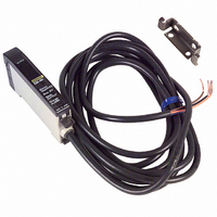
E3X-NH11
Description
SENSOR PHOTO AMP FIBEROPTIC NPN
Manufacturer
Omron
Type
High Precision Fiber Optic Amplifierr
Series
E3X-NHr
Specifications of E3X-NH11
Output Type
NPN
Amplifier Type
General Purpose
Voltage - Supply
12 V ~ 24 V
Current - Supply
75mA
Mounting Type
DIN Rail
Features
Three mode for optimal sensing
Light Source
Red LED
Connection
Pre-leaded
Output Configuration
NPN
Sensor Output
NPN
Switch Terminals
Cable
Supply Voltage Min
12V
Peak Reflow Compatible (260 C)
No
Sensor Input
Fiber Optic
Supply Voltage Max
24V
Leaded Process Compatible
No
Rohs Compliant
No
Fiber Optic Sensor Type
General Purpose
Lead Free Status / RoHS Status
Contains lead / RoHS compliant by exemption
Lead Free Status / RoHS Status
Contains lead / RoHS non-compliant, Contains lead / RoHS compliant by exemption
Other names
E3XNH11
Z1110
Z1110
Available stocks
Company
Part Number
Manufacturer
Quantity
Price
Company:

Part Number:
E3X-NH11
Manufacturer:
OMRON
Quantity:
475


Installation
J CUTTING FIBER
Insert a fiber into the Fiber Cutter and determine the length of the
fiber to be cut.
Press down the Fiber Cutter in a single stroke to cut the fiber.
An insertion mark can be placed on the fiber to serve as a
reference when inserting the fiber into the Amplifier. Use the
following procedure.
Confirm through the Cutter hole that the fiber is inserted beyond
the insertion mark hole so that the insertion mark is properly
indicated, and then press firmly down on the Cutter.
Insert the fiber into the Amplifier up to the insertion mark. Proper
fiber performance will not be achieved unless the fiber is inserted
all the way to the insertion mark. (This method is applicable to
standard, 2.2-mm-diameter fibers only.)
E3X-NH
(1)
(2)
Lock button
J FIBER CONNECTION OR
The E3X-NH Amplifier has a lock button. Follow these steps to
connect or disconnect the fibers to (or from) the E3X-NH
Amplifier:
Note:
Connection
1. After cutting the fibers (using the E39-F4 Fiber Cutter), place
2. Insert the fiber into the Amplifier up to this insertion mark.
3. Press the lock button to lock the fiber in that position.
an insertion mark on the fiber so that it can be correctly in-
serted into the Amplifier.
DISCONNECTION PROCEDURES
The fiber must be locked or released in a temperature
range of --10°C to 40°C (14°F to 104°F).
Fiber
Fiber insertion mark
E3X-NH
13
Related parts for E3X-NH11
Image
Part Number
Description
Manufacturer
Datasheet
Request
R

Part Number:
Description:
SENSOR PHOTO AMP FIBEROPTC W/TMR
Manufacturer:
Omron
Datasheet:
Part Number:
Description:
SENSOR PHOTO AMP FIBEROPTC W/TMR
Manufacturer:
Omron
Datasheet:
Part Number:
Description:
SENSOR PHOTO AMP FIBEROPTIC PNP
Manufacturer:
Omron
Datasheet:

Part Number:
Description:
AUTOTUNE NPN
Manufacturer:
Omron
Datasheet:
Part Number:
Description:
AUTOTUNE NPN TMR REMOTE TCH
Manufacturer:
Omron
Datasheet:
Part Number:
Description:
AUTOTUNE PNP TMR REMOTE TCH
Manufacturer:
Omron
Datasheet:

Part Number:
Description:
PREWIRED DIGITAL NPN FO AMP
Manufacturer:
Omron
Datasheet:
Part Number:
Description:
PREWIRED DIGITAL PNP FO AMP
Manufacturer:
Omron
Datasheet:

Part Number:
Description:
PREWIRED DIGITAL PNP BLUE LED
Manufacturer:
Omron
Datasheet:

Part Number:
Description:
G6S-2GLow Signal Relay
Manufacturer:
Omron Corporation
Datasheet:
Part Number:
Description:
Compact, Low-cost, SSR Switching 5 to 20 A
Manufacturer:
Omron Corporation
Datasheet:
Part Number:
Description:
Manufacturer:
Omron Corporation
Datasheet: