E3X-NH51 Omron, E3X-NH51 Datasheet
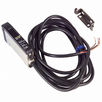
E3X-NH51
Specifications of E3X-NH51
Z1113


Related parts for E3X-NH51


E3X-NH51 Summary of contents
Page 1
... E3X-NH41 E3X-NH21 PNP open collector, NPN open collector, load current load current max residual voltage: max., residual voltage: max., residual voltage: max residual voltage max max. E3X-NH PNP E3X-NH51 PNP open collector, load current max., residual voltage: max residual voltage max. ...
Page 2
... Z directions 20 MΩ min. (at 500 VDC) 2 500 m/s (approx. 50G) for 3 times each and Z axis IEC IP50 2m cable PBT Polycarbonate Approx. 100 g Mounting brackets (included) E3X-NH Timer-function models E3X-NH21 E3X-NH51 NPN PNP 40 ms off delay 2 (approx. 30G) for 2 hrs each and 3 ...
Page 3
... UP/DOWN Selector Select UP for increasing the threshold value. Select DOWN for decreasing the threshold value. Operation Mode Selector Switchable between light-ON and dark-ON modes. Operation J OUTPUT CIRCUITS E3X-NH11 (NPN output) Photo- electric sensor main circuit J OPERATION MODE Light-ON Light received Light not received ...
Page 4
... Environments Reason Dust sticking to the fiber tip. Targets are slightly different from each other in color or surface quality. Detecting Passing Chip Parts E3X-NH E32-L25A E3X-NH 3.3 mm Auto-tuning (Automatic Sensitivity Compensation) E3X-NH Sensitivity Setting Without Objects Application Examples Detection of minute passing ob- jects. Detection of lead wires. ...
Page 5
... E3X-NH J SENSITIVITY SETTING (TEACHING) The sensitivity of the E3X-NH is factory-set to maximum. When resetting the sensitivity of the E3X-NH to maximum after with/without-ob- ject teaching or positioning/no-object teaching, follow the steps described below. Maximum Sensitivity Setting 1. Set the mode selector to TEACH. Hold the SET button down for three seconds. Be sure that all the threshold indicators (red) are lit ...
Page 6
... Be sure that all the threshold indicators (red) are lit. The built-in buzzer will beep once when the threshold indicators are lit. 2. Set the mode selector to RUN. The threshold is set automati- cally. Mark 3. The Sensor will automatically compensate for environmental changes. E3X-NH Press once for 0 ...
Page 7
... Manual-tuning (Fine Sensitivity Adjustment) Note: The auto-tuning function will be disabled if manual-tuning is utilized. 1. After setting the sensitivity of the E3X-NH, select the adjust- ment direction with the UP/DOWN selector in the ADJ mode. (2) (1) 2. Press the SET button in ADJ mode. Be sure that the threshold-level changes whenever the SET button is pressed. If two threshold indicators are lit, the threshold will automatically be set to a middle value equal to the target’ ...
Page 8
... RUN/ADJ Mode The number of the incident level indicators lit depends on the position of the target. When using the manual-tuning function possible to adjust the threshold in six levels. The default threshold is set to 7. Fiber head E3X- Farther Target Threshold Light Incident Threshold level ...
Page 9
... Press the SET button without target in the sensing area. Set the threshold to the value that is ±6% of the incident level. Farther Light Closer 2. Detecting the first object in RUN/ADJ mode. Farther Light Closer 18% Tuning range 18% E3X-NH Threshold 6% 6% Incident level without a fixed Threshold background or target. Incident Threshold level indicator indicator 18% 6% ...
Page 10
... After the threshold has been compensated, the Threshold Indicator will flash, indicating the adjusted value. • Threshold compensation occurs 10, 15, 22, and 30 minutes after turning on the E3X-NH. After the initial 30 minute time- • frame, Threshold Compensation is continually repeated, every 30-minutes. Alarm output will occur if the threshold compensation range is not within the tuning range. Perform sensitivity setting again if the alarm • ...
Page 11
... Standard length Weight: Approx. 100 g 12 Operation indicator Threshold indicators (A) (see note) Incident level indicators Two, 2.4 dia. Two, 3.2-dia. holes E3X-NH Note: The mounting bracket can be at- tached to this side. Mounting bracket Two, mounting holes ...
Page 12
... J FIBER CONNECTION OR DISCONNECTION PROCEDURES The E3X-NH Amplifier has a lock button. Follow these steps to connect or disconnect the fibers to (or from) the E3X-NH Amplifier: Note: The fiber must be locked or released in a temperature range of --10° ...
Page 13
... Observe the Following Precautions when Using the Reflector (E39-R3) Use detergent, etc., to remove any dust or oil from the surfaces where tape is applied. Adhesive tape will not be attached properly if oil or dust remains on the surface. The E39-R3 cannot be used in places where it is exposed to oil or chemicals. E3X- ...
Page 14
... DIN rail. This could decrease the mount- ing strength of the Amplifier Unit. (2) (1) DIN Rail Removal You can remove the Amplifier in one easy step: 1. Press the Amplifier Unit in direction (A) and lift the fiber inser- tion part in direction (B) as shown here (B) DIN Rail (A) E3X-NH 15 ...
Page 15
... Note that this will not have an effect on performance since no control output will be generated. Perform two-point teaching if two to three Fiber Units are closely mounted together, at which time supply power only to the Unit in teaching operation in turn or block the emitters of the Fiber Units not in teaching operation. E3X-NH Fiber Unit ...
Page 16
... Do not assume that all Units ensure such operations. J WHEN THE POWER IS OFF The moment power is turned off, the E3X-NH may output a pulse signal which could affect the operation of the devices connected to it. This will occur more often if power is supplied to the E3X-NH from an external power supply, thus affecting the connected timer or counter ...