E3X-NH21 Omron, E3X-NH21 Datasheet - Page 14
E3X-NH21
Manufacturer Part Number
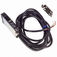
E3X-NH21
Description
SENSOR PHOTO AMP FIBEROPTC W/TMR
Manufacturer
Omron
Series
E3X-NHr
Type
High Precision Fiber Optic Amplifierr
Datasheet
1.E3X-NH21.pdf
(16 pages)
Specifications of E3X-NH21
Amplifier Type
Timer Function
Voltage - Supply
12 V ~ 24 V
Output Type
NPN
Current - Supply
75mA
Mounting Type
DIN Rail
Features
Three mode for optimal sensing
Light Source
Red LED
Connection
Pre-leaded
Output Configuration
NPN
Lead Free Status / RoHS Status
Contains lead / RoHS compliant by exemption
Lead Free Status / RoHS Status
Contains lead / RoHS compliant by exemption, Lead free / RoHS Compliant
Other names
E3XNH21
Z1112
Z1112


J ATTACHMENT UNITS
Applications
E39-F10 Fiber Connector
Use the following procedure (refer to the figure) to connect fibers
via the Fiber Connector.
Each Fiber Unit should be as close as possible before they are
connected.
Sensing distance will be reduced by approximately 25% when
fibers are connected.
Only fibers with a 2.2-mm dia. can be connected. (Refer to page
NO TAG for applicable Fiber Units.)
Protective Spiral Tube
Insert a fiber to the Protective Spiral Tube from the head
connector side (threaded) of the tube.
Push the fiber into the Protective Spiral Tube. The tube should be
straight so that the fiber is not twisted when inserted. Then turn
the end cap of the spiral tube.
Secure the Protective Spiral Tube on a suitable place with the
attached nut.
E3X-NH
Retention unit
Protective spiral
tube
Protective spiral
tube
Mounting panel
Protective spiral
tube
Splice
Fiber Unit
Fiber Unit
Toothed washer
Retention unit
Hexagon clamping nut
Fiber Unit
Fiber Unit
Use the attached saddle to secure the end cap of the Protective
Spiral Tube. To secure the Protective Spiral Tube at a position
other than the end cap, apply tape to the tube so that the portion
becomes thicker in diameter.
J AMPLIFIER UNITS
Mounting
1. Mount the front part (see #1) to the mounting bracket (attach-
2. Press the back part (see #2) onto the mounting bracket or
Note:
Removal
You can remove the Amplifier in one easy step:
1. Press the Amplifier Unit in direction (A) and lift the fiber inser-
(B)
ment) or on a DIN rail.
onto the DIN rail.
tion part in direction (B) as shown here
DO NOT mount the back part on the mounting bracket or
the DIN rail first and then mount the front part on the mount-
ing bracket on the DIN rail. This could decrease the mount-
ing strength of the Amplifier Unit.
(A)
(1)
DIN Rail
DIN Rail
(2)
End cap
Saddle
Tube
E3X-NH
15
Related parts for E3X-NH21
Image
Part Number
Description
Manufacturer
Datasheet
Request
R

Part Number:
Description:
SENSOR PHOTO AMP FIBEROPTC W/TMR
Manufacturer:
Omron
Datasheet:
Part Number:
Description:
SENSOR PHOTO AMP FIBEROPTIC PNP
Manufacturer:
Omron
Datasheet:
Part Number:
Description:
SENSOR PHOTO AMP FIBEROPTIC NPN
Manufacturer:
Omron
Datasheet:

Part Number:
Description:
AUTOTUNE NPN
Manufacturer:
Omron
Datasheet:
Part Number:
Description:
AUTOTUNE NPN TMR REMOTE TCH
Manufacturer:
Omron
Datasheet:
Part Number:
Description:
AUTOTUNE PNP TMR REMOTE TCH
Manufacturer:
Omron
Datasheet:

Part Number:
Description:
PREWIRED DIGITAL NPN FO AMP
Manufacturer:
Omron
Datasheet:
Part Number:
Description:
PREWIRED DIGITAL PNP FO AMP
Manufacturer:
Omron
Datasheet:

Part Number:
Description:
PREWIRED DIGITAL PNP BLUE LED
Manufacturer:
Omron
Datasheet:

Part Number:
Description:
G6S-2GLow Signal Relay
Manufacturer:
Omron Corporation
Datasheet:
Part Number:
Description:
Compact, Low-cost, SSR Switching 5 to 20 A
Manufacturer:
Omron Corporation
Datasheet:
Part Number:
Description:
Manufacturer:
Omron Corporation
Datasheet: