USBLC6-2SC6 STMicroelectronics, USBLC6-2SC6 Datasheet - Page 6
USBLC6-2SC6
Manufacturer Part Number
USBLC6-2SC6
Description
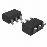
IC ESD PROTECTION LO CAP SOT23-6
Manufacturer
STMicroelectronics
Datasheet
1.USBLC6-2P6.pdf
(14 pages)
Specifications of USBLC6-2SC6
Voltage - Working
5V
Voltage - Clamping
6V
Technology
Mixed Technology
Number Of Circuits
2
Applications
USB
Package / Case
SOT-23-6
Polarity
Bidirectional
Channels
2 Channels
Clamping Voltage
17 V
Operating Voltage
5 V
Breakdown Voltage
6 V
Termination Style
SMD/SMT
Peak Surge Current
5 A
Capacitance
3.5 pF
Maximum Operating Temperature
+ 125 C
Minimum Operating Temperature
- 40 C
Dimensions
1.75 (Max) mm W x 3.05 (Max) mm L
Diode Type
Low Capacitance / ESD Protection
Clamping Voltage Vc Max
17V
Diode Case Style
SOT-23
No. Of Pins
6
Rohs Compliant
Yes
Lead Free Status / RoHS Status
Lead free / RoHS Compliant
Power (watts)
-
Lead Free Status / Rohs Status
Lead free / RoHS Compliant
Other names
497-5235-2
USBLC6-2SC6
USBLC6-2SC6
Available stocks
Company
Part Number
Manufacturer
Quantity
Price
Company:

Part Number:
USBLC6-2SC6
Manufacturer:
ST
Quantity:
6 000
Part Number:
USBLC6-2SC6
Manufacturer:
ST
Quantity:
20 000
Company:
Part Number:
USBLC6-2SC6H/C
Manufacturer:
STM
Quantity:
239
Part Number:
USBLC6-2SC6Y
Manufacturer:
ST
Quantity:
20 000


Technical information
Important:
2.4
2.4.1
6/14
Figure 9.
Vout
Vin
A good precaution to take is to put the protection device as close as possible to the
disturbance source (generally the connector).
Crosstalk behavior
Crosstalk phenomenon
Figure 11. Crosstalk phenomenon
The crosstalk phenomenon is due to the coupling between 2 lines. The coupling factor ( 12
or 21) increases when the gap across lines decreases, particularly in silicon dice. In the
above example the expected signal on load R
has got an extra value
crosstalk phenomenon of the line 1 on the line 2. This phenomenon has to be taken into
account when the drivers impose fast digital data or high frequency analog signals in the
disturbing line. The perturbed line will be more affected if it works with low voltage signal or
high load impedance (few k ).
ESD response to IEC 61000-4-2
(+15 kV air discharge)
V
G1
V
G2
DRIVERS
R
G1
R
21
G2
V
G1
. This part of the V
Line 1
Line 2
Figure 10. ESD response to IEC 61000-4-2
Vout
Vin
L2
is
G1
2
signal represents the effect of the
V
(-15 kV air discharge)
RECEIVERS
G2
R
, in fact the real voltage at this point
L2
R
L1
2
V
G2
+
1
21
V
V
G1
G1
+
12
USBLC6-2
V
G2
Related parts for USBLC6-2SC6
Image
Part Number
Description
Manufacturer
Datasheet
Request
R

Part Number:
Description:
IC ESD PROTECTION HS SOT-666
Manufacturer:
STMicroelectronics
Datasheet:

Part Number:
Description:
IC ESD PROTECTION HS SOT23-6
Manufacturer:
STMicroelectronics
Datasheet:

Part Number:
Description:
VERY LOW CAPACITANCE ESD PROTECTION
Manufacturer:
STMicroelectronics
Datasheet:
Part Number:
Description:
Very low capacitance ESD protection
Manufacturer:
STMicroelectronics
Datasheet:
Part Number:
Description:
STMicroelectronics [RIPPLE-CARRY BINARY COUNTER/DIVIDERS]
Manufacturer:
STMicroelectronics
Datasheet:
Part Number:
Description:
STMicroelectronics [LIQUID-CRYSTAL DISPLAY DRIVERS]
Manufacturer:
STMicroelectronics
Datasheet:

Part Number:
Description:
BOARD EVAL FOR MEMS SENSORS
Manufacturer:
STMicroelectronics
Datasheet:
Part Number:
Description:
NPN TRANSISTOR POWER MODULE
Manufacturer:
STMicroelectronics
Datasheet:
Part Number:
Description:
TURBOSWITCH ULTRA-FAST HIGH VOLTAGE DIODE
Manufacturer:
STMicroelectronics
Datasheet:
Part Number:
Description:
Manufacturer:
STMicroelectronics
Datasheet:
Part Number:
Description:
DIODE / SCR MODULE
Manufacturer:
STMicroelectronics
Datasheet:
Part Number:
Description:
DIODE / SCR MODULE
Manufacturer:
STMicroelectronics
Datasheet: