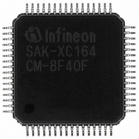
SAK-XC164CM-8F40F AA Infineon Technologies, SAK-XC164CM-8F40F AA Datasheet - Page 54

SAK-XC164CM-8F40F AA
Manufacturer Part Number
SAK-XC164CM-8F40F AA
Description
IC MCU 16BIT 64KB FLSH TQFP-64-8
Manufacturer
Infineon Technologies
Series
XC16xr
Datasheet
1.SAF-XC164CM-4F20F_AA.pdf
(70 pages)
Specifications of SAK-XC164CM-8F40F AA
Core Processor
C166SV2
Core Size
16-Bit
Speed
40MHz
Connectivity
CAN, SPI, UART/USART
Peripherals
PWM, WDT
Number Of I /o
47
Program Memory Size
64KB (64K x 8)
Program Memory Type
FLASH
Ram Size
6K x 8
Voltage - Supply (vcc/vdd)
2.35 V ~ 2.7 V
Data Converters
A/D 14x8/10b
Oscillator Type
Internal
Operating Temperature
-40°C ~ 125°C
Package / Case
64-LFQFP
Data Bus Width
16 bit
Data Ram Size
6 KB
Interface Type
2xASC, 2xSSC
Maximum Clock Frequency
40 MHz
Number Of Programmable I/os
47
Number Of Timers
9
Operating Supply Voltage
5 V
Maximum Operating Temperature
+ 125 C
Mounting Style
SMD/SMT
Minimum Operating Temperature
- 40 C
On-chip Adc
10 bit, 14 Channel
Packages
PG-LQFP-64
Max Clock Frequency
40.0 MHz
Sram (incl. Cache)
6.0 KByte
Can Nodes
2
A / D Input Lines (incl. Fadc)
14
Program Memory
64.0 KByte
For Use With
B158-H8961-X-X-7600IN - KIT EASY XC164CMXC164CMUCANIN - KIT U-CAN STARTER XC164CMMCBX167-NET - BOARD EVAL INFINEON CAN/ETHRNTMCBXC167-BASIC - BOARD EVAL BASIC INFINEON XC16X
Lead Free Status / RoHS Status
Lead free / RoHS Compliant
Eeprom Size
-
Lead Free Status / Rohs Status
Details
Other names
SAK-XC164CM-8F40FAACT
SAK-XC164CM-8F40FAACT
SAK-XC164CM-8F40FAAINCT
SAK-XC164CM-8F40FAACT
SAK-XC164CM-8F40FAAINCT
Table 11
Parameter
XTAL1 input current
Pin capacitance
(digital inputs/outputs)
1) Keeping signal levels within the limits specified in this table, ensures operation without overload conditions.
2) If XTAL1 is driven by a crystal, reaching an amplitude (peak to peak) of 0.4 ×
3) This parameter is tested for P3, P9.
4) The maximum deliverable output current of a port driver depends on the selected output driver mode, see
5) As a rule, with decreasing output current the output levels approach the respective supply level (
6) This specification is not valid for outputs which are switched to open drain mode. In this case the respective
7) An additional error current (
8) The driver of P3.15 is designed for faster switching, because this pin can deliver the system clock (CLKOUT).
9) During a hardware reset this specification is valid for configuration on P1H.4, P1H.5, P9.4 and P9.5.
10) The maximum current may be drawn while the respective signal line remains inactive.
11) The minimum current must be drawn to drive the respective signal line active.
12) Not subject to production test - verified by design/characterization.
Table 12
Port Output Driver
Mode
Strong driver
Medium driver
Weak driver
1) An output current above |
Data Sheet
For signal levels outside these specifications, also refer to the specification of the overload current
Table
V
output will float and the voltage results from the external circuitry.
the definition of the overload coupling factor
The maximum leakage current for P3.15 is, therefore, increased to 1 μA.
After a hardware reset this specification is valid for NMI.
For any group of 16 neighboring port output pins the total output current in each direction (Σ
remain below 50 mA.
OH
→
12,
V
DDP
Current Limits for Port Output
). However, only the levels for nominal output currents are guaranteed.
DC Characteristics (Operating Conditions apply)
Current Limits for Port Output Drivers
12)
I
OXnom
Maximum Output Current
(
10 mA
4.0 mA
0.5 mA
I
I
Symbol
I
C
INJ
IL
OLmax
IO
) will flow if an overload current flows through an adjacent pin. Please refer to
| may be drawn from up to three pins at the same time.
, -
I
OHmax
CC –
CC –
Drivers. The limit for pin groups must be respected.
K
OV
)
Min.
1)
.
52
Limit Values
Max.
±20
10
Nominal Output Current
(
2.5 mA
1.0 mA
0.1 mA
I
OLnom
, -
V
Unit Test Condition
μA
pF
1)
Electrical Parameters
DDI
I
OHnom
(cont’d)
is sufficient.
0 V <
–
)
I
OL
Derivatives
V1.4, 2007-03
and Σ-
XC164CM
V
IN
V
<
I
OL
I
OV
OH
V
→
.
) must
DDI
V
SS
,


