MC68711E20CFNE3 Freescale Semiconductor, MC68711E20CFNE3 Datasheet - Page 52
MC68711E20CFNE3
Manufacturer Part Number
MC68711E20CFNE3
Description
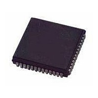
IC MCU 8BIT 52-PLCC
Manufacturer
Freescale Semiconductor
Series
HC11r
Datasheet
1.MC711D3CFNE2R.pdf
(138 pages)
Specifications of MC68711E20CFNE3
Core Processor
HC11
Core Size
8-Bit
Speed
3MHz
Connectivity
SCI, SPI
Peripherals
POR, WDT
Number Of I /o
38
Program Memory Size
20KB (20K x 8)
Program Memory Type
OTP
Eeprom Size
512 x 8
Ram Size
768 x 8
Voltage - Supply (vcc/vdd)
4.5 V ~ 5.5 V
Data Converters
A/D 8x8b
Oscillator Type
Internal
Operating Temperature
-40°C ~ 85°C
Package / Case
52-PLCC
Processor Series
M687xx
Core
HC11
Data Bus Width
8 bit
Data Ram Size
768 B
Interface Type
SCI, SPI
Maximum Clock Frequency
3 MHz
Number Of Programmable I/os
38
Number Of Timers
8
Maximum Operating Temperature
+ 85 C
Mounting Style
SMD/SMT
Minimum Operating Temperature
- 40 C
On-chip Adc
8 bit, 8 Channel
Lead Free Status / RoHS Status
Lead free / RoHS Compliant
Available stocks
Company
Part Number
Manufacturer
Quantity
Price
Company:

Part Number:
MC68711E20CFNE3
Manufacturer:
TI
Quantity:
101
Company:
Part Number:
MC68711E20CFNE3
Manufacturer:
Freescale Semiconductor
Quantity:
10 000


Resets, Interrupts, and Low-Power Modes
When an I bit related interrupt occurs, the I bit is automatically set by hardware after stacking the CCR
byte. The X bit is not affected. When an X bit related interrupt occurs, both the X and the I bit are
automatically set by hardware after stacking the CCR. A return-from-interrupt (RTI) instruction restores
the X and I bits to their preinterrupt request state.
4.3.5 Priority Structure
Interrupts obey a fixed hardware priority circuit to resolve simultaneous requests. However one I bit
related interrupt source may be elevated to the highest I bit priority in the resolution circuit.
Six interrupt sources are not masked by the I bit in the CCR and have these fixed priority relationships:
SWI is actually an instruction and has highest priority, other than resets, in that once the SWI opcode is
fetched, no other interrupt can be honored until the SWI vector has been fetched.
Each of the previous sources is an input to the priority resolution circuit. The highest I bit masked priority
input to the resolution circuit is assigned to be connected to any one of the remaining I bit related interrupt
sources. This assignment is made under the software control of the HPRIO register. To avoid timing
races, the HPRIO register can be written only while the I bit related interrupts are inhibited (I bit of CCR
is logic 1). An interrupt that is assigned to this higher priority position is still subject to masking by any
associated control bits or by the I bit in the CCR. The interrupt vector address is not affected by assigning
a source to the higher priority position.
Figure
Figure 4-4
fetches.
Figure 4-6
sources within the SCI subsystem.
52
1. Reset
2. Clock monitor failure
3. COP failure
4. Illegal opcode
5. SWI
6. XIRQ
4-4,
Figure 4-5
shows how the CPU begins from a reset, and how interrupt detection relates to normal opcode
is an expansion of the SCI interrupt block of
Figure
4-5, and
is an expansion of a block in
Figure 4-6
MC68HC711D3 Data Sheet, Rev. 2.1
illustrate the interrupt process as it relates to normal processing.
Figure 4-4
Figure 4-4
and shows how interrupt priority is resolved.
and shows the resolution of interrupt
Freescale Semiconductor
Related parts for MC68711E20CFNE3
Image
Part Number
Description
Manufacturer
Datasheet
Request
R

Part Number:
Description:
Manufacturer:
Freescale Semiconductor, Inc
Datasheet:
Part Number:
Description:
Manufacturer:
Freescale Semiconductor, Inc
Datasheet:
Part Number:
Description:
Manufacturer:
Freescale Semiconductor, Inc
Datasheet:
Part Number:
Description:
Manufacturer:
Freescale Semiconductor, Inc
Datasheet:
Part Number:
Description:
Manufacturer:
Freescale Semiconductor, Inc
Datasheet:
Part Number:
Description:
Manufacturer:
Freescale Semiconductor, Inc
Datasheet:
Part Number:
Description:
Manufacturer:
Freescale Semiconductor, Inc
Datasheet:
Part Number:
Description:
Manufacturer:
Freescale Semiconductor, Inc
Datasheet:
Part Number:
Description:
Manufacturer:
Freescale Semiconductor, Inc
Datasheet:
Part Number:
Description:
Manufacturer:
Freescale Semiconductor, Inc
Datasheet:
Part Number:
Description:
Manufacturer:
Freescale Semiconductor, Inc
Datasheet:
Part Number:
Description:
Manufacturer:
Freescale Semiconductor, Inc
Datasheet:
Part Number:
Description:
Manufacturer:
Freescale Semiconductor, Inc
Datasheet:
Part Number:
Description:
Manufacturer:
Freescale Semiconductor, Inc
Datasheet:
Part Number:
Description:
Manufacturer:
Freescale Semiconductor, Inc
Datasheet: