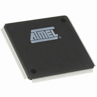
AT91M63200-25AI Atmel, AT91M63200-25AI Datasheet - Page 4

AT91M63200-25AI
Manufacturer Part Number
AT91M63200-25AI
Description
IC ARM7 MCU 176 TQFP
Manufacturer
Atmel
Series
AT91SAMr
Datasheets
1.AT91M43300-25CI.pdf
(21 pages)
2.AT91M43300-25CI.pdf
(5 pages)
3.AT91M63200-25AI.pdf
(12 pages)
4.AT91M63200-25AI.pdf
(153 pages)
Specifications of AT91M63200-25AI
Core Processor
ARM7
Core Size
16/32-Bit
Speed
25MHz
Connectivity
EBI/EMI, SPI, UART/USART
Peripherals
POR, WDT
Number Of I /o
58
Program Memory Type
OTP
Ram Size
2K x 8
Voltage - Supply (vcc/vdd)
1.8 V ~ 3.6 V
Oscillator Type
External
Operating Temperature
-40°C ~ 85°C
Package / Case
176-TQFP, 176-VQFP
Lead Free Status / RoHS Status
Contains lead / RoHS non-compliant
Eeprom Size
-
Program Memory Size
-
Data Converters
-
Available stocks
Company
Part Number
Manufacturer
Quantity
Price
5. AT91M63200 Datasheet – Page 99
4. AT91M63200 Datasheet – Page 141
3. Initializing SPI in Master Mode May Cause a Mode Fault Detection:
2. SPI in Slave Mode Does not Work
1. Parity Error Bit (PARE) is Set Too Early
4
Problem Fix/Workaround
The reset value of the Status Register does not need to be defined at zero. The status of the SPI is updated at each
cycle after the reset and the SPENDRX and SPENDTX bits are set, because the PDC counters are 0.
Problem Fix/Workaround
The correct description of the CPU bit is:
0 = CPU clock is disabled
1 = CPU clock is enabled
Problem Fix/Workaround
PA26/NPCS0/NSS pin must be pulled up to the V
PA26/NPCS0/NSS must be defined as a peripheral pin before programming the SPI peripheral.
In transmission, the data to be transmitted (written in SP_TDR) is transferred into the shift register and, consequently,
the TDRE bit in SP_SR is set to 1. Though the transfer has not begun, when the following data is written in SP_TDR, it
is also transferred into the shift register, crushing the preceding data and setting the bit TDRE to 1.
Problem Fix/Workaround
No workaround available.
The Parity Error bit on the USART is set as soon as the parity bit is detected. However, the faulty character reception
status (RXRDY) is set afterwards, only when the stop bit is detected. This is particularly unfortunate when working in
Multi-drop mode, as the PARE bit identifies the Address Bytes. When it is detected, the corresponding character has
not yet been transferred in the US_RHR register and, therefore, is not yet available.
Problem Fix/Workaround
No problem fix/workaround to propose.
AT91M63200/AT91M43300 Errata Sheet
DDIO
power supply.
1781B–01/02


