Z86E4412VSG Zilog, Z86E4412VSG Datasheet - Page 26
Z86E4412VSG
Manufacturer Part Number
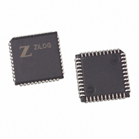
Z86E4412VSG
Description
IC MICROCONTROLLER 16K 44-PLCC
Manufacturer
Zilog
Series
Z8®r
Datasheet
1.Z86E4412PSG.pdf
(58 pages)
Specifications of Z86E4412VSG
Core Processor
Z8
Core Size
8-Bit
Speed
12MHz
Connectivity
EBI/EMI
Peripherals
POR, WDT
Number Of I /o
32
Program Memory Size
16KB (16K x 8)
Program Memory Type
OTP
Ram Size
236 x 8
Voltage - Supply (vcc/vdd)
3.5 V ~ 5.5 V
Oscillator Type
Internal
Operating Temperature
0°C ~ 70°C
Package / Case
44-LCC (J-Lead)
Processor Series
Z86E4xx
Core
Z8
Data Bus Width
8 bit
Data Ram Size
237 B
Maximum Clock Frequency
12 MHz
Number Of Programmable I/os
32
Number Of Timers
2
Operating Supply Voltage
3.5 V to 5.5 V
Maximum Operating Temperature
+ 70 C
Mounting Style
SMD/SMT
Development Tools By Supplier
Z86E4400ZDV, Z86E4400ZDP, Z86E4400ZDF, Z86E3400ZDV, Z86E3400ZDS, Z86E3400ZDP, Z86C4001ZDV
Minimum Operating Temperature
0 C
For Use With
309-1042 - ADAPTER 44-PLCC ZIF TO 44-PLCC309-1041 - ADAPTER 44-PLCC TO 44-PLCC309-1038 - ADAPTER 44-PLCC ZIF TO 40-DIP309-1037 - ADAPTER 44-PLCC TO 40-DIP
Lead Free Status / RoHS Status
Lead free / RoHS Compliant
Eeprom Size
-
Data Converters
-
Lead Free Status / Rohs Status
Details
Other names
269-3981
Z86E4412VSG
Z86E4412VSG
Available stocks
Company
Part Number
Manufacturer
Quantity
Price


Z86E33/733/E34/E43/743/E44
CMOS Z8 OTP Microcontrollers
PIN FUNCTIONS
EPROM Programming Mode
D7-D0 Data Bus. The data can be read from or written to
external memory through the data bus.
V
EPROM read mode and 6V during other modes.
/CE Chip Enable (active Low). This pin is active during
EPROM Read Mode, Program Mode, and Program Verify
Mode.
/OE Output Enable (active Low). This pin drives the direc-
tion of the Data Bus. When this pin is Low, the Data Bus is
output, when High, the Data Bus is input.
EPM EPROM Program Mode. This pin controls the differ-
ent EPROM Program Mode by applying different voltages.
V
age.
/PGM Program Mode (active Low). When this pin is Low,
the data is programmed to the EPROM through the Data
Bus.
CLR Clear (active High). This pin resets the internal ad-
dress counter at the High Level.
CLK Address Clock. This pin is a clock input. The internal
address counter increases by one for each clock cycle.
Application Precaution
The production test-mode environment may be enabled
accidentally during normal operation if excessive noise
surges above V
In addition, processor operation of Z8 OTP devices may be
affected by excessive noise surges on the V
pins while the microcontroller is in Standard Mode.
Recommendations for dampening voltage surges in both
test and OTP mode include the following:
Standard Mode
XTAL Crystal 1 (time-based input). This pin connects a
parallel-resonant crystal, ceramic resonator, LC, RC net-
work, or external single-phase clock to the on-chip oscilla-
tor input.
26
CC
PP
Using a clamping diode to V
Adding a capacitor to the affected pin
Enable EPROM/Test Mode Disable OTP option bit.
Program Voltage. This pin supplies the program volt-
Power Supply. This pin must supply 5V during the
CC
occur on pins P31 and /RESET.
CC
PP
, EPM, /OE
P R E L I M I N A R Y
XTAL2 Crystal 2 (time-based output). This pin connects a
parallel-resonant crystal, ceramic resonator, LC, or RC
network to the on-chip oscillator output.
R//W Read/Write (output, write Low). The R//W signal is
Low when the CCP is writing to the external program or
data memory (
/RESET Reset (input, active Low). Reset will initialize the
MCU. Reset is accomplished either through Power-On,
Watch-Dog Timer reset, STOP-Mode Recovery, or exter-
nal reset. During Power-On Reset and Watch-Dog Timer
Reset, the internally generated reset drives the reset pin
low for the POR time. Any devices driving the reset line
must be open-drain in order to avoid damage from a pos-
sible conflict during reset conditions. Pull-up is provided in-
ternally. After the POR time, /RESET is a Schmitt-trig-
gered input. (/Reset is available on Z86E43/743/E44 only.)
To avoid asynchronous and noisy reset problems, the
Z86E43/743/E44
nal clocks (4TpC). If the external reset signal is less than
4TpC in duration, no reset occurs. On the fifth clock after
the reset is detected, an internal RST signal is latched and
held for an internal register count of 18 external clocks, or
for the duration of the external reset, whichever is longer.
During the reset cycle, /DS is held active Low while /AS cy-
cles at a rate of TpC/2. Program execution begins at loca-
tion 000CH, 5-10 TpC cycles after /RESET is released. For
Power-On Reset, the reset output time is 5 ms. The
Z86E43/743/E44
P3M registers on a STOP-Mode Recovery operation.
/ROMless (input, active Low). This pin, when connected to
GND, disables the internal ROM and forces the device to
function as a Z86C90/C89 ROMless Z8. (Note that, when
left unconnected or pulled High to V
tions normally as a Z8 ROM version).
Note: When using in ROM Mode in High EMI (noisy) envi-
ronment, the ROMless pins should be connected directly
to V
/DS (output, active Low). Data Strobe is activated once for
each external memory transfer. For a READ operation,
data must be available prior to the trailing edge of /DS. For
WRITE operations, the falling edge of /DS indicates that
output data is valid.
/AS (output, active Low). Address Strobe is pulsed once at
the beginning of each machine cycle for external memory
transfer. Address output is from Port 0/Port 1 for all exter-
nal programs. Memory address transfers are valid at the
trailing edge of /AS. Under program control, /AS is placed
in the high-impedance state along with Ports 0 and 1, Data
Strobe, and Read/Write.
CC
.
Z86E43/743/E44 only
is equipped with a reset filter of four exter-
does not reset WDTMR, SMR, P2M, and
).
CC
, the device func-
DS97Z8X1500
Zilog
Related parts for Z86E4412VSG
Image
Part Number
Description
Manufacturer
Datasheet
Request
R

Part Number:
Description:
Communication Controllers, ZILOG INTELLIGENT PERIPHERAL CONTROLLER (ZIP)
Manufacturer:
Zilog, Inc.
Datasheet:

Part Number:
Description:
KIT DEV FOR Z8 ENCORE 16K TO 64K
Manufacturer:
Zilog
Datasheet:

Part Number:
Description:
KIT DEV Z8 ENCORE XP 28-PIN
Manufacturer:
Zilog
Datasheet:

Part Number:
Description:
DEV KIT FOR Z8 ENCORE 8K/4K
Manufacturer:
Zilog
Datasheet:

Part Number:
Description:
KIT DEV Z8 ENCORE XP 28-PIN
Manufacturer:
Zilog
Datasheet:

Part Number:
Description:
DEV KIT FOR Z8 ENCORE 4K TO 8K
Manufacturer:
Zilog
Datasheet:
Part Number:
Description:
CMOS Z8 microcontroller. ROM 16 Kbytes, RAM 256 bytes, speed 16 MHz, 32 lines I/O, 3.0V to 5.5V
Manufacturer:
Zilog, Inc.
Datasheet:
Part Number:
Description:
Low-cost microcontroller. 512 bytes ROM, 61 bytes RAM, 8 MHz
Manufacturer:
Zilog, Inc.
Datasheet:
Part Number:
Description:
Z8 4K OTP Microcontroller
Manufacturer:
Zilog, Inc.
Datasheet:
Part Number:
Description:
CMOS SUPER8 ROMLESS MCU
Manufacturer:
Zilog, Inc.
Datasheet:
Part Number:
Description:
SL1866 CMOSZ8 OTP Microcontroller
Manufacturer:
Zilog, Inc.
Datasheet:
Part Number:
Description:
SL1866 CMOSZ8 OTP Microcontroller
Manufacturer:
Zilog, Inc.
Datasheet:
Part Number:
Description:
OTP (KB) = 1, RAM = 125, Speed = 12, I/O = 14, 8-bit Timers = 2, Comm Interfaces Other Features = Por, LV Protect, Voltage = 4.5-5.5V
Manufacturer:
Zilog, Inc.
Datasheet:
Part Number:
Description:
Manufacturer:
Zilog, Inc.
Datasheet: