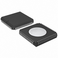
P80C592FFA/00,512 NXP Semiconductors, P80C592FFA/00,512 Datasheet - Page 16

P80C592FFA/00,512
Manufacturer Part Number
P80C592FFA/00,512
Description
IC 80C51 MCU 8BIT ROMLESS 68PLCC
Manufacturer
NXP Semiconductors
Series
80Cr
Datasheet
1.P80C592FFA00512.pdf
(108 pages)
Specifications of P80C592FFA/00,512
Program Memory Type
ROMless
Package / Case
68-PLCC
Core Processor
8051
Core Size
8-Bit
Speed
16MHz
Connectivity
CAN, EBI/EMI, UART/USART
Peripherals
DMA, POR, PWM, WDT
Number Of I /o
48
Ram Size
512 x 8
Voltage - Supply (vcc/vdd)
4.5 V ~ 5.5 V
Data Converters
A/D 8x10b
Oscillator Type
Internal
Operating Temperature
-40°C ~ 85°C
Processor Series
P80C5x
Core
80C51
Data Bus Width
8 bit
Data Ram Size
512 B
Interface Type
CAN/UART
Maximum Clock Frequency
16 MHz
Number Of Programmable I/os
40
Number Of Timers
3
Maximum Operating Temperature
+ 85 C
Mounting Style
SMD/SMT
3rd Party Development Tools
PK51, CA51, A51, ULINK2
Minimum Operating Temperature
- 40 C
On-chip Adc
8-ch x 10-bit
Cpu Family
80C
Device Core
80C51
Device Core Size
8b
Frequency (max)
16MHz
Program Memory Size
Not Required
Total Internal Ram Size
512Byte
# I/os (max)
40
Number Of Timers - General Purpose
3
Operating Supply Voltage (typ)
5V
Operating Supply Voltage (max)
5.5V
Operating Supply Voltage (min)
4.5V
Instruction Set Architecture
CISC
Operating Temp Range
-40C to 85C
Operating Temperature Classification
Industrial
Mounting
Surface Mount
Pin Count
68
Package Type
PLCC
Lead Free Status / RoHS Status
Lead free / RoHS Compliant
Eeprom Size
-
Program Memory Size
-
Lead Free Status / Rohs Status
Compliant
Other names
568-1241-5
935086530512
P80C592FFAA
935086530512
P80C592FFAA
Available stocks
Company
Part Number
Manufacturer
Quantity
Price
Company:
Part Number:
P80C592FFA/00,512
Manufacturer:
ON
Quantity:
300
Company:
Part Number:
P80C592FFA/00,512
Manufacturer:
NXP Semiconductors
Quantity:
10 000
Philips Semiconductors
Notes to the alternative Port functions
1. Port lines P1.6 and P1.7 may be selected as CTX0 and CTX1 outputs of the serial port SIO1 (CAN).
2. Unused analog inputs can be used as digital inputs. As Port 5 lines may be used as inputs to the ADC, these digital
9
Two Pulse Width Modulated (PWM) output channels are
available with the P8xC592. These channels provide
output pulses of programmable length and interval.
The repetition frequency is defined by an 8-bit prescaler
PWMP which generates the clock for the counter.
Both the prescaler and counter are common to both PWM
channels. The 8-bit counter counts modulo 255 i.e. from
0 to 254 inclusive. The value of the 8-bit counter is
compared to the contents of two registers:
PWM0 and PWM1.
Provided the contents of either of these registers is greater
than the counter value, the output of PWM0 or PWM1 is
set LOW. If the contents of these register are equal to, or
less than the counter value, the output will be HIGH. The
pulse-width-ratio is therefore defined by the contents of the
register PWM0 and PWM1. The pulse-width-ratio is in the
range of 0 to
increments of
1996 Jun 27
handbook, full pagewidth
8-bit microcontroller with on-chip CAN
After reset P1.6 and P1.7 may be used as normal I/O ports, if the CAN interface is not used.
inputs have an inherent hysteresis to prevent the input logic from drawing too much current from the power lines
when driven by analog signals.
Channel-to-channel crosstalk should be taken into consideration when both digital and analog signals are
simultaneously input to Port 5 (see Chapter 20).
PULSE WIDTH MODULATED OUTPUTS (PWM)
from port latch
read port pin
255
1
input data
255
255
.
and may be programmed in
Q
Fig.8 I/O buffers in the P8xC592 (P1.0 to P1.5, Ports 2, 3, and 4).
2 oscillator
periods
BUFFER
INPUT
strong pull-up
16
The repetition frequency f
given by:
When using an oscillator frequency of 16 MHz, for
example, the above formula would give a repetition
frequency range of 123 Hz to 31.4 kHz.
By loading the PWM registers with either 00H or FFH, the
PWM outputs can be retained at a constant HIGH or LOW
level respectively. When loading FFH to the PWM
registers, the 8-bit counter will never actually reach this
(FFH) value.
Both output pins PWMn are driven by push-pull drivers,
and are not shared with any other function.
p1
n
f
PWM
p2
=
------------------------------------------------------------- -
2
I1
PWMP
PWM
p3
f
CLK
, at the PWMn outputs is
+
1
1, 2, 3 or 4
Product specification
+5 V
I/O PIN
PORT
255
MGA153
P8xC592


