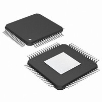
PIC24FJ256DA106-I/PT Microchip Technology, PIC24FJ256DA106-I/PT Datasheet - Page 267

PIC24FJ256DA106-I/PT
Manufacturer Part Number
PIC24FJ256DA106-I/PT
Description
MCU PIC 16BIT FLASH 256K 64TQFP
Manufacturer
Microchip Technology
Series
PIC® 24Fr
Specifications of PIC24FJ256DA106-I/PT
Core Size
16-Bit
Program Memory Size
256KB (85.5K x 24)
Core Processor
PIC
Speed
32MHz
Connectivity
I²C, IrDA, SPI, UART/USART, USB OTG
Peripherals
Brown-out Detect/Reset, GFX, LVD, POR, PWM, WDT
Number Of I /o
52
Program Memory Type
FLASH
Ram Size
24K x 8
Voltage - Supply (vcc/vdd)
2.2 V ~ 3.6 V
Data Converters
A/D 16x10b
Oscillator Type
Internal
Operating Temperature
-40°C ~ 85°C
Package / Case
64-TFQFP
Controller Family/series
PIC24
No. Of I/o's
52
Ram Memory Size
24KB
Cpu Speed
32MHz
No. Of Timers
5
Interface
I2C, SPI, UART, USB
Embedded Interface Type
I2C, SPI, UART, USB
Rohs Compliant
Yes
Processor Series
PIC24FJ
Core
PIC
Data Bus Width
16 bit
Data Ram Size
24 KB
Interface Type
I2C, SPI, UART
Maximum Clock Frequency
32 MHz
Number Of Programmable I/os
29
Number Of Timers
5
Operating Supply Voltage
2.2 V to 3.6 V
Maximum Operating Temperature
+ 85 C
Mounting Style
SMD/SMT
3rd Party Development Tools
52713-733, 52714-737, 53276-922, EWDSPIC
Development Tools By Supplier
PG164130, DV164035, DV244005, DV164005, AC164127-4, AC164127-6, AC164139, DM240001, DM240312, DV164039
Minimum Operating Temperature
- 40 C
On-chip Adc
10 bit, 16 Channel
Lead Free Status / RoHS Status
Lead free / RoHS Compliant
Eeprom Size
-
Lead Free Status / Rohs Status
Details
Available stocks
Company
Part Number
Manufacturer
Quantity
Price
Company:
Part Number:
PIC24FJ256DA106-I/PT
Manufacturer:
Microchip Technology
Quantity:
10 000
- Current page: 267 of 408
- Download datasheet (4Mb)
REGISTER 18-17: U1IR: USB INTERRUPT STATUS REGISTER (HOST MODE ONLY)
2010 Microchip Technology Inc.
bit 15
bit 7
Legend:
R = Readable bit
-n = Value at POR
bit 15-8
bit 7
bit 6
bit 5
bit 4
bit 3
bit 2
bit 1
bit 0
R/K-0, HS
Note:
STALLIF
U-0
—
Individual bits can only be cleared by writing a ‘1’ to the bit position as part of a word write operation on the
entire register. Using Boolean instructions or bitwise operations to write to a single bit position will cause
all set bits at the moment of the write to become cleared.
Unimplemented: Read as ‘0’
STALLIF: STALL Handshake Interrupt bit
1 = A STALL handshake was sent by the peripheral device during the handshake phase of the
0 = A STALL handshake has not been sent
ATTACHIF: Peripheral Attach Interrupt bit
1 = A peripheral attachment has been detected by the module; it is set if the bus state is not SE0 and
0 = No peripheral attacement has been detected
RESUMEIF: Resume Interrupt bit
1 = A K-state is observed on the D+ or D- pin for 2.5 s (differential ‘1’ for low speed, differential ‘0’ for
0 = No K-state is observed
IDLEIF: Idle Detect Interrupt bit
1 = Idle condition is detected (constant Idle state of 3 ms or more)
0 = No Idle condition is detected
TRNIF: Token Processing Complete Interrupt bit
1 = Processing of the current token is complete; read the U1STAT register for endpoint information
0 = Processing of the current token not complete; clear the U1STAT register or load the next token
SOFIF: Start-Of-Frame Token Interrupt bit
1 = A Start-Of-Frame token received by the peripheral or the Start-Of-Frame threshold reached by the host
0 = No Start-Of-Frame token received or threshold reached
UERRIF: USB Error Condition Interrupt bit
1 = An unmasked error condition has occurred; only error states enabled in the U1EIE register can set
0 = No unmasked error condition has occurred
DETACHIF: Detach Interrupt bit
1 = A peripheral detachment has been detected by the module; Reset state must be cleared before
0 = No peripheral detachment is detected. Individual bits can only be cleared by writing a ‘1’ to the bit
ATTACHIF
R/K-0, HS
transaction in Device mode
there has been no bus activity for 2.5 s
full speed)
from U1STAT
this bit
this bit can be reasserted
position as part of a word write operation on the entire register. Using Boolean instructions or bit-
wise operations to write to a single bit position will cause all set bits at the moment of the write to
become cleared.
U-0
—
U = Unimplemented bit, read as ‘0’
K = Write ‘1’ to clear bit
‘1’ = Bit is set
RESUMEIF
R/K-0, HS
U-0
—
R/K-0, HS
PIC24FJ256DA210 FAMILY
IDLEIF
U-0
—
HS = Hardware Settable bit
‘0’ = Bit is cleared
R/K-0, HS
TRNIF
U-0
—
R/K-0, HS
SOFIF
U-0
—
x = Bit is unknown
UERRIF
U-0
R-0
—
DS39969B-page 267
DETACHIF
R/K-0, HS
U-0
—
bit 8
bit 0
Related parts for PIC24FJ256DA106-I/PT
Image
Part Number
Description
Manufacturer
Datasheet
Request
R

Part Number:
Description:
Manufacturer:
Microchip Technology Inc.
Datasheet:

Part Number:
Description:
Manufacturer:
Microchip Technology Inc.
Datasheet:

Part Number:
Description:
Manufacturer:
Microchip Technology Inc.
Datasheet:

Part Number:
Description:
Manufacturer:
Microchip Technology Inc.
Datasheet:

Part Number:
Description:
Manufacturer:
Microchip Technology Inc.
Datasheet:

Part Number:
Description:
Manufacturer:
Microchip Technology Inc.
Datasheet:

Part Number:
Description:
Manufacturer:
Microchip Technology Inc.
Datasheet:

Part Number:
Description:
Manufacturer:
Microchip Technology Inc.
Datasheet:


