C8051F017R Silicon Laboratories Inc, C8051F017R Datasheet - Page 3
C8051F017R
Manufacturer Part Number
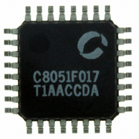
C8051F017R
Description
IC 8051 MCU 32K FLASH 32LQFP
Manufacturer
Silicon Laboratories Inc
Series
C8051F01xr
Specifications of C8051F017R
Core Processor
8051
Core Size
8-Bit
Speed
25MHz
Connectivity
SMBus (2-Wire/I²C), SPI, UART/USART
Peripherals
Brown-out Detect/Reset, POR, PWM, Temp Sensor, WDT
Number Of I /o
8
Program Memory Size
32KB (32K x 8)
Program Memory Type
FLASH
Ram Size
2.25K x 8
Voltage - Supply (vcc/vdd)
2.7 V ~ 3.6 V
Data Converters
A/D 4x10b; D/A 2x12b
Oscillator Type
Internal
Operating Temperature
-40°C ~ 85°C
Package / Case
32-LQFP
Lead Free Status / RoHS Status
Contains lead / RoHS non-compliant
Eeprom Size
-
Other names
336-1042-2
Q1057388
Q1057388
Available stocks
Company
Part Number
Manufacturer
Quantity
Price
Company:

Part Number:
C8051F017R
Manufacturer:
Silicon Laboratories Inc
Quantity:
10 000


6.
7.
8.
9.
10. CIP-51 CPU.......................................................................................................................... 62
3
C8051F000/1/2/5/6/7
C8051F010/1/2/5/6/7
Table 5.1. 12-Bit ADC Electrical Characteristics..............................................................................................38
Table 5.1. 12-Bit ADC Electrical Characteristics..............................................................................................39
ADC (10-Bit, C8051F010/1/2/5/6/7 Only).......................................................................... 40
Figure 6.1. 10-Bit ADC Functional Block Diagram..........................................................................................40
6.1.
6.2.
Figure 6.2. 10-Bit ADC Track and Conversion Example Timing.....................................................................41
Figure 6.3. Temperature Sensor Transfer Function...........................................................................................42
Figure 6.4. AMX0CF: AMUX Configuration Register (C8051F01x) ..............................................................42
Figure 6.5. AMX0SL: AMUX Channel Select Register (C8051F01x).............................................................43
Figure 6.6. ADC0CF: ADC Configuration Register (C8051F01x)...................................................................44
Figure 6.7. ADC0CN: ADC Control Register (C8051F01x) ............................................................................45
Figure 6.8. ADC0H: ADC Data Word MSB Register (C8051F01x) ...............................................................46
Figure 6.9. ADC0L: ADC Data Word LSB Register (C8051F01x).................................................................46
6.3.
Figure 6.10. ADC0GTH: ADC Greater-Than Data High Byte Register (C8051F01x) ....................................47
Figure 6.11. ADC0GTL: ADC Greater-Than Data Low Byte Register (C8051F01x) .....................................47
Figure 6.12. ADC0LTH: ADC Less-Than Data High Byte Register (C8051F01x) .........................................47
Figure 6.13. ADC0LTL: ADC Less-Than Data Low Byte Register (C8051F01x)...........................................47
Figure 6.14. 10-Bit ADC Window Interrupt Examples, Right Justified Data...................................................48
Figure 6.15. 10-Bit ADC Window Interrupt Examples, Left Justified Data .....................................................48
Figure 6.15. 10-Bit ADC Window Interrupt Examples, Left Justified Data .....................................................49
Table 6.1. 10-Bit ADC Electrical Characteristics..............................................................................................49
Table 6.1. 10-Bit ADC Electrical Characteristics..............................................................................................50
DACs, 12 BIT VOLTAGE MODE..................................................................................... 51
Figure 7.1. DAC Functional Block Diagram......................................................................................................51
Figure 7.2. DAC0H: DAC0 High Byte Register ...............................................................................................52
Figure 7.3. DAC0L: DAC0 Low Byte Register ................................................................................................52
Figure 7.4. DAC0CN: DAC0 Control Register.................................................................................................52
Figure 7.5. DAC1H: DAC1 High Byte Register ...............................................................................................53
Figure 7.6. DAC1L: DAC1 Low Byte Register ................................................................................................53
Figure 7.7. DAC1CN: DAC1 Control Register.................................................................................................53
Table 7.1. DAC Electrical Characteristics.........................................................................................................54
COMPARATORS ............................................................................................................... 55
Figure 8.1. Comparator Functional Block Diagram ..........................................................................................55
Figure 8.2. Comparator Hysteresis Plot.............................................................................................................56
Figure 8.3. CPT0CN: Comparator 0 Control Register ......................................................................................57
Figure 8.4. CPT1CN: Comparator 1 Control Register ......................................................................................58
Table 8.1. Comparator Electrical Characteristics ..............................................................................................59
VOLTAGE REFERENCE ................................................................................................. 60
Figure 9.1. Voltage Reference Functional Block Diagram ...............................................................................60
Figure 9.2. REF0CN: Reference Control Register ............................................................................................61
Table 9.1. Reference Electrical Characteristics .................................................................................................61
Figure 10.1. CIP-51 Block Diagram..................................................................................................................62
10.1.
Table 10.1. CIP-51 Instruction Set Summary....................................................................................................65
10.2.
Figure 10.2. Memory Map.................................................................................................................................69
10.3.
Table 10.2. Special Function Register Memory Map ........................................................................................70
Table 10.3. Special Function Registers .............................................................................................................70
Figure 10.3. SP: Stack Pointer...........................................................................................................................74
Figure 10.4. DPL: Data Pointer Low Byte ........................................................................................................74
Analog Multiplexer and PGA..................................................................................................................40
ADC Modes of Operation........................................................................................................................41
ADC Programmable Window Detector...................................................................................................47
INSTRUCTION SET...........................................................................................................................63
MEMORY ORGANIZATION ............................................................................................................68
SPECIAL FUNCTION REGISTERS..................................................................................................70
Rev. 1.7
Related parts for C8051F017R
Image
Part Number
Description
Manufacturer
Datasheet
Request
R

Part Number:
Description:
SMD/C°/SINGLE-ENDED OUTPUT SILICON OSCILLATOR
Manufacturer:
Silicon Laboratories Inc
Part Number:
Description:
Manufacturer:
Silicon Laboratories Inc
Datasheet:
Part Number:
Description:
N/A N/A/SI4010 AES KEYFOB DEMO WITH LCD RX
Manufacturer:
Silicon Laboratories Inc
Datasheet:
Part Number:
Description:
N/A N/A/SI4010 SIMPLIFIED KEY FOB DEMO WITH LED RX
Manufacturer:
Silicon Laboratories Inc
Datasheet:
Part Number:
Description:
N/A/-40 TO 85 OC/EZLINK MODULE; F930/4432 HIGH BAND (REV E/B1)
Manufacturer:
Silicon Laboratories Inc
Part Number:
Description:
EZLink Module; F930/4432 Low Band (rev e/B1)
Manufacturer:
Silicon Laboratories Inc
Part Number:
Description:
I°/4460 10 DBM RADIO TEST CARD 434 MHZ
Manufacturer:
Silicon Laboratories Inc
Part Number:
Description:
I°/4461 14 DBM RADIO TEST CARD 868 MHZ
Manufacturer:
Silicon Laboratories Inc
Part Number:
Description:
I°/4463 20 DBM RFSWITCH RADIO TEST CARD 460 MHZ
Manufacturer:
Silicon Laboratories Inc
Part Number:
Description:
I°/4463 20 DBM RADIO TEST CARD 868 MHZ
Manufacturer:
Silicon Laboratories Inc
Part Number:
Description:
I°/4463 27 DBM RADIO TEST CARD 868 MHZ
Manufacturer:
Silicon Laboratories Inc
Part Number:
Description:
I°/4463 SKYWORKS 30 DBM RADIO TEST CARD 915 MHZ
Manufacturer:
Silicon Laboratories Inc
Part Number:
Description:
N/A N/A/-40 TO 85 OC/4463 RFMD 30 DBM RADIO TEST CARD 915 MHZ
Manufacturer:
Silicon Laboratories Inc
Part Number:
Description:
I°/4463 20 DBM RADIO TEST CARD 169 MHZ
Manufacturer:
Silicon Laboratories Inc