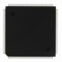
HD6417041AVF16V Renesas Electronics America, HD6417041AVF16V Datasheet - Page 430

HD6417041AVF16V
Manufacturer Part Number
HD6417041AVF16V
Description
IC SUPERH MCU ROMLESS 144QFP
Manufacturer
Renesas Electronics America
Series
SuperH® SH7040r
Specifications of HD6417041AVF16V
Core Processor
SH-2
Core Size
32-Bit
Speed
28.7MHz
Connectivity
EBI/EMI, SCI
Peripherals
DMA, POR, PWM, WDT
Number Of I /o
98
Program Memory Type
ROMless
Ram Size
4K x 8
Voltage - Supply (vcc/vdd)
3 V ~ 3.6 V
Data Converters
A/D 8x10b
Oscillator Type
Internal
Operating Temperature
-20°C ~ 75°C
Package / Case
144-QFP
Lead Free Status / RoHS Status
Lead free / RoHS Compliant
Eeprom Size
-
Program Memory Size
-
Available stocks
Company
Part Number
Manufacturer
Quantity
Price
Company:
Part Number:
HD6417041AVF16V
Manufacturer:
Renesas Electronics America
Quantity:
10 000
- Current page: 430 of 531
- Download datasheet (3Mb)
Section 7 Pipeline Operation
The slots in which MA and IF contend are split into two cycles. MA is given priority to execute in
the first half (when there is a WB, it immediately follows the MA), and the EX, ID, and IF are
executed simultaneously in the latter half. For example, in figure 7.6 the MA of instruction 1 is
executed in slot D while the EX of instruction 2, the ID of instruction 3 and IF of instruction 4 are
executed simultaneously thereafter. In slot E, the MA of instruction 2 is given priority and the EX
of instruction 3, the ID of instruction 4 and the IF of instruction 5 executed thereafter.
The number of cycles for a slot in which MA and IF are in contention is the sum of the number of
memory access cycles for the MA and the number of memory access cycles for the IF.
The Relationship Between IF and the Location of Instructions in On-Chip ROM/RAM or
On-Chip Memory (SH1 and SH2): When the instruction is located in the on-chip memory
(ROM or RAM) or on-chip cache of the SuperH microcomputer, the SuperH microcomputer
accesses the on-chip memory in 32-bit units. The SuperH microcomputer instructions are all fixed
at 16 bits, so basically 2 instructions can be fetched in a single IF stage access.
If an instruction is located on a longword boundary, an IF can get two instructions at each
instruction fetch. The IF of the next instruction does not generate a bus cycle to fetch an
instruction from memory. Since the next instruction IF also fetches two instructions, the
instruction IFs after that do not generate a bus cycle either.
This means that IFs of instructions that are located so they start from the longword boundaries
within instructions located in on-chip memory (the position when the bottom two bits of the
instruction address are 00 is A1 = 0 and A0 = 0) also fetch two instructions. The IF of the next
instruction does not generate a bus cycle. IFs that do not generate bus cycles are written in lower
case as ‘if’. These ‘if’s always take one state.
When branching results in a fetch from an instruction located so it starts from the word boundaries
(the position when the bottom two bits of the instruction address are 10 is A1 = 1, A0 = 0), the bus
cycle of the IF fetches only the specified instruction more than one of said instructions. The IF of
the next instruction thus generates a bus cycle, and fetches two instructions. Figure 7.7 illustrates
these operations.
Rev. 5.00 Jun 30, 2004 page 414 of 512
REJ09B0171-0500O
Related parts for HD6417041AVF16V
Image
Part Number
Description
Manufacturer
Datasheet
Request
R

Part Number:
Description:
KIT STARTER FOR M16C/29
Manufacturer:
Renesas Electronics America
Datasheet:

Part Number:
Description:
KIT STARTER FOR R8C/2D
Manufacturer:
Renesas Electronics America
Datasheet:

Part Number:
Description:
R0K33062P STARTER KIT
Manufacturer:
Renesas Electronics America
Datasheet:

Part Number:
Description:
KIT STARTER FOR R8C/23 E8A
Manufacturer:
Renesas Electronics America
Datasheet:

Part Number:
Description:
KIT STARTER FOR R8C/25
Manufacturer:
Renesas Electronics America
Datasheet:

Part Number:
Description:
KIT STARTER H8S2456 SHARPE DSPLY
Manufacturer:
Renesas Electronics America
Datasheet:

Part Number:
Description:
KIT STARTER FOR R8C38C
Manufacturer:
Renesas Electronics America
Datasheet:

Part Number:
Description:
KIT STARTER FOR R8C35C
Manufacturer:
Renesas Electronics America
Datasheet:

Part Number:
Description:
KIT STARTER FOR R8CL3AC+LCD APPS
Manufacturer:
Renesas Electronics America
Datasheet:

Part Number:
Description:
KIT STARTER FOR RX610
Manufacturer:
Renesas Electronics America
Datasheet:

Part Number:
Description:
KIT STARTER FOR R32C/118
Manufacturer:
Renesas Electronics America
Datasheet:

Part Number:
Description:
KIT DEV RSK-R8C/26-29
Manufacturer:
Renesas Electronics America
Datasheet:

Part Number:
Description:
KIT STARTER FOR SH7124
Manufacturer:
Renesas Electronics America
Datasheet:

Part Number:
Description:
KIT STARTER FOR H8SX/1622
Manufacturer:
Renesas Electronics America
Datasheet:

Part Number:
Description:
KIT DEV FOR SH7203
Manufacturer:
Renesas Electronics America
Datasheet:


