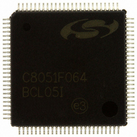
C8051F064-GQ Silicon Laboratories Inc, C8051F064-GQ Datasheet - Page 11

C8051F064-GQ
Manufacturer Part Number
C8051F064-GQ
Description
IC 8051 MCU 64K FLASH 100TQFP
Manufacturer
Silicon Laboratories Inc
Series
C8051F06xr
Specifications of C8051F064-GQ
Program Memory Type
FLASH
Program Memory Size
64KB (64K x 8)
Package / Case
100-TQFP, 100-VQFP
Core Processor
8051
Core Size
8-Bit
Speed
25MHz
Connectivity
EBI/EMI, SMBus (2-Wire/I²C), SPI, UART/USART
Peripherals
Brown-out Detect/Reset, POR, PWM, WDT
Number Of I /o
59
Ram Size
4.25K x 8
Voltage - Supply (vcc/vdd)
2.7 V ~ 3.6 V
Data Converters
A/D 2x16b
Oscillator Type
Internal
Operating Temperature
-40°C ~ 85°C
Processor Series
C8051F0x
Core
8051
Data Bus Width
8 bit
Data Ram Size
4.25 KB
Interface Type
I2C, SMBus, SPI, UART
Maximum Clock Frequency
25 MHz
Number Of Programmable I/os
59
Number Of Timers
5
Operating Supply Voltage
2.7 V to 3.6 V
Maximum Operating Temperature
+ 85 C
Mounting Style
SMD/SMT
3rd Party Development Tools
PK51, CA51, A51, ULINK2
Development Tools By Supplier
C8051F060DK
Minimum Operating Temperature
- 40 C
On-chip Adc
16 bit, 1 Channel
On-chip Dac
12 bit, 2 Channel
No. Of I/o's
59
Ram Memory Size
4352Byte
Cpu Speed
25MHz
No. Of Timers
5
Rohs Compliant
Yes
Package
100TQFP
Device Core
8051
Family Name
C8051F06x
Maximum Speed
25 MHz
Data Rom Size
64 KB
A/d Bit Size
16 bit
A/d Channels Available
1
Height
1.05 mm
Length
14 mm
Supply Voltage (max)
3.6 V
Supply Voltage (min)
2.7 V
Width
14 mm
Lead Free Status / RoHS Status
Lead free / RoHS Compliant
For Use With
336-1219 - KIT EVAL FOR C8051F064
Eeprom Size
-
Lead Free Status / Rohs Status
Lead free / RoHS Compliant
Other names
336-1218
Available stocks
Company
Part Number
Manufacturer
Quantity
Price
Company:
Part Number:
C8051F064-GQ
Manufacturer:
SiliconL
Quantity:
28
Company:
Part Number:
C8051F064-GQ
Manufacturer:
Silicon Laboratories Inc
Quantity:
10 000
Company:
Part Number:
C8051F064-GQR
Manufacturer:
Silicon Laboratories Inc
Quantity:
10 000
Part Number:
C8051F064-GQR
Manufacturer:
SILICONLABS/芯科
Quantity:
20 000
8. DACs, 12-Bit Voltage Mode (DAC0 and DAC1, C8051F060/1/2/3) .................... 103
9. Voltage Reference 2 (C8051F060/2) .................................................................... 111
10. Voltage Reference 2 (C8051F061/3) ................................................................... 113
11. Voltage Reference 2 (C8051F064/5/6/7) .............................................................. 115
12. Comparators ......................................................................................................... 117
13. CIP-51 Microcontroller ......................................................................................... 123
Figure 7.14. ADC2LTL: ADC2 Less-Than Data Low Byte Register ......................... 98
Figure 7.15. ADC Window Compare Example: Right-Justified Single-Ended Data . 99
Figure 7.16. ADC Window Compare Example: Left-Justified Single-Ended Data.... 99
Figure 7.17. ADC Window Compare Example: Right-Justified Differential Data.... 100
Figure 7.18. ADC Window Compare Example: Left-Justified Differential Data ...... 100
Figure 8.1. DAC Functional Block Diagram............................................................ 103
Figure 8.2. DAC0H: DAC0 High Byte Register ...................................................... 105
Figure 8.3. DAC0L: DAC0 Low Byte Register........................................................ 105
Figure 8.4. DAC0CN: DAC0 Control Register........................................................ 106
Figure 8.5. DAC1H: DAC1 High Byte Register ...................................................... 107
Figure 8.6. DAC1L: DAC1 Low Byte Register........................................................ 107
Figure 8.7. DAC1CN: DAC1 Control Register........................................................ 108
Figure 9.1. Voltage Reference Functional Block Diagram ..................................... 111
Figure 9.2. REF2CN: Reference Control Register 2 .............................................. 112
Figure 10.1. Voltage Reference Functional Block Diagram.................................... 113
Figure 10.2. REF2CN: Reference Control Register 2 ............................................ 114
Figure 11.1. Voltage Reference Functional Block Diagram.................................... 115
Figure 11.2. REF2CN: Reference Control Register 2 ............................................ 116
Figure 12.1. Comparator Functional Block Diagram .............................................. 117
Figure 12.2. Comparator Hysteresis Plot ............................................................... 118
Figure 12.3. CPTnCN: Comparator 0, 1, and 2 Control Register ........................... 120
Figure 12.4. CPTnMD: Comparator Mode Selection Register ............................... 121
Figure 13.1. CIP-51 Block Diagram....................................................................... 124
Figure 13.2. Memory Map ...................................................................................... 130
Figure 13.3. SFR Page Stack................................................................................. 133
Figure 13.4. SFR Page Stack While Using SFR Page 0x0F To Access Port 5...... 134
Figure 13.5. SFR Page Stack After ADC2 Window Comparator Interrupt Occurs . 135
Figure 13.6. SFR Page Stack Upon PCA Interrupt Occurring During an ADC2 ISR....
Figure 13.7. SFR Page Stack Upon Return From PCA Interrupt ........................... 137
Figure 13.8. SFR Page Stack Upon Return From ADC2 Window Interrupt ........... 138
Figure 13.9. SFRPGCN: SFR Page Control Register ............................................ 139
Figure 13.10. SFRPAGE: SFR Page Register ....................................................... 139
Figure 13.11. SFRNEXT: SFR Next Register......................................................... 140
Figure 13.12. SFRLAST: SFR Last Register.......................................................... 140
Figure 13.13. SP: Stack Pointer ............................................................................. 148
Figure 13.14. DPL: Data Pointer Low Byte............................................................. 148
Figure 13.15. DPH: Data Pointer High Byte ........................................................... 148
Figure 13.16. PSW: Program Status Word............................................................. 149
136
Rev. 1.2
C8051F060/1/2/3/4/5/6/7
11


