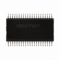
M38507F8AFP#U1 Renesas Electronics America, M38507F8AFP#U1 Datasheet - Page 41

M38507F8AFP#U1
Manufacturer Part Number
M38507F8AFP#U1
Description
IC 740/3850 MCU FLASH 42SSOP
Manufacturer
Renesas Electronics America
Series
740/38000r
Datasheet
1.M38507F8AFPU1.pdf
(61 pages)
Specifications of M38507F8AFP#U1
Core Processor
740
Core Size
8-Bit
Speed
12.5MHz
Connectivity
SIO, UART/USART
Peripherals
PWM, WDT
Number Of I /o
32
Program Memory Size
32KB (32K x 8)
Program Memory Type
FLASH
Ram Size
1K x 8
Voltage - Supply (vcc/vdd)
1.8 V ~ 5.5 V
Data Converters
A/D 9x10b
Oscillator Type
Internal
Operating Temperature
-20°C ~ 85°C
Package / Case
42-SSOP
Package
42SSOP
Family Name
740
Maximum Speed
12.5 MHz
Operating Supply Voltage
5 V
Data Bus Width
8 Bit
Number Of Programmable I/os
34
Interface Type
UART
On-chip Adc
9-chx10-bit
Number Of Timers
4
Lead Free Status / RoHS Status
Lead free / RoHS Compliant
Eeprom Size
-
Available stocks
Company
Part Number
Manufacturer
Quantity
Price
3850 Group (Spec.A QzROM version)
Rev.2.13
REJ03B0125-0213
[MISRG (MISRG)] 0038
MISRG consists of three control bits (bits 1 to 3) for middle-
speed mode automatic switch and one control bit (bit 0) for
oscillation stabilizing time set after STP instruction released.
By setting the middle-speed mode automatic switch start bit to
“1” while operating in the low-speed mode and setting the
middle-speed mode automatic switch set bit to “1”, X
oscillation automatically starts and the mode is automatically
switched to the middle-speed mode.
Fig 45. System clock generating circuit block diagram (Single-chip mode)
Notes1: Any one of high-speed, middle-speed or low-speed mode is selected by bits 7 and 6 of the CPU mode register.
Interrupt disable flag l
2: f(X
3: When bit 0 of MISRG = “0”, the prescaler 12 is set to “FF
4: Although a feed-back resistor exists on-chip, an external feed-back resistor may be needed depending on conditions.
When low-speed mode is selected, set port X
count source at executing STP instruction.
When bit 0 of MISRG = “1”, set the sufficient time for oscillation of used oscillator to stabilize since nothing is set to the prescaler 12 and timer 1.
Interrupt request
Apr 17, 2009
IN
)/16 is supplied as the count source to the prescaler 12 at reset, the count source before executing the STP instruction is supplied as the
X
CIN
X
IN
Q
(Note 4)
16
S
R
“1”
Reset
X
COUT
X
STP
instruction
OUT
Page 39 of 56
“0”
Port X
switch bit
Main clock stop bit
High-speed or
middle-speed mode
Main clock division ratio
selection bits (Note 1)
C
low-speed mode
C
switch bit (b4) to “1”.
1/2
instruction
High-speed or
Low-speed mode
WIT
16
1/4
” and timer 1 is set to “01
IN
S
R
Main clock division ratio
selection bits (Note 1)
1/2
Q
Middle-speed mode
Fig 44. Structure of MISRG
b7
Note: When the mode is automatically switched from the low-speed mode to the
Timer 12 count
source selection bit
middle-speed mode, the value of CPU mode register (address 003B
changes.
Q
16
”.
S
R
Prescaler 12
STP
instruction
b0
Timing φ (internal clock)
(Note 3)
MISRG
(MISRG : address 0038
Oscillation stabilizing time set after STP instruction
released bit
Middle-speed mode automatic switch set bit
Middle-speed mode automatic switch wait time set bit
Middle-speed mode automatic switch start bit
(Depending on program)
Not used (return “0” when read)
0: Automatically set “01
1: Automatically set nothing
0: Not set automatically
1: Automatic switching enable
0: 6.5 to 7.5 machine cycles
1: 4.5 to 5.5 machine cycles
0: Invalid
1: Automatic switch start
“FF
16
” to Prescaler 12
Timer 1
Reset or
STP instruction
(Note 2)
16
Reset
16
)
” to Timer 1,
16
)


