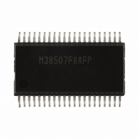
M38507F8AFP#U1 Renesas Electronics America, M38507F8AFP#U1 Datasheet - Page 21

M38507F8AFP#U1
Manufacturer Part Number
M38507F8AFP#U1
Description
IC 740/3850 MCU FLASH 42SSOP
Manufacturer
Renesas Electronics America
Series
740/38000r
Datasheet
1.M38507F8AFPU1.pdf
(61 pages)
Specifications of M38507F8AFP#U1
Core Processor
740
Core Size
8-Bit
Speed
12.5MHz
Connectivity
SIO, UART/USART
Peripherals
PWM, WDT
Number Of I /o
32
Program Memory Size
32KB (32K x 8)
Program Memory Type
FLASH
Ram Size
1K x 8
Voltage - Supply (vcc/vdd)
1.8 V ~ 5.5 V
Data Converters
A/D 9x10b
Oscillator Type
Internal
Operating Temperature
-20°C ~ 85°C
Package / Case
42-SSOP
Package
42SSOP
Family Name
740
Maximum Speed
12.5 MHz
Operating Supply Voltage
5 V
Data Bus Width
8 Bit
Number Of Programmable I/os
34
Interface Type
UART
On-chip Adc
9-chx10-bit
Number Of Timers
4
Lead Free Status / RoHS Status
Lead free / RoHS Compliant
Eeprom Size
-
Available stocks
Company
Part Number
Manufacturer
Quantity
Price
3850 Group (Spec.A QzROM version)
Rev.2.13
REJ03B0125-0213
INTERRUPTS
Interrupts occur by 15 sources among 15 sources: six external,
eight internal, and one software.
• Interrupt Control
Each interrupt is controlled by an interrupt request bit, an
interrupt enable bit, and the interrupt disable flag except for the
software interrupt set by the BRK instruction. An interrupt
occurs if the corresponding interrupt request and enable bits are
“1” and the interrupt disable flag is “0”.
Interrupt enable bits can be set or cleared by software.
Interrupt request bits can be cleared by software, but cannot be
set by software.
The BRK instruction cannot be disabled with any flag or bit. The
I (interrupt disable) flag disables all interrupts except the BRK
instruction interrupt.
When several interrupts occur at the same time, the interrupts are
received according to priority.
• Interrupt Operation
By acceptance of an interrupt, the following operations are
automatically performed:
1. The contents of the program counter and the processor sta-
2. The interrupt disable flag is set and the corresponding inter-
3. The interrupt jump destination address is read from the vec-
tus register are automatically pushed onto the stack.
rupt request bit is cleared.
tor table into the program counter.
Apr 17, 2009
Page 19 of 56
<Notes>
When setting the followings, the interrupt request bit may be set
to “1”.
When not requiring for the interrupt occurrence synchronized
with these setting, take the following sequence.
(1) Set the corresponding interrupt enable bit to “0” (disabled).
(2) Set the interrupt edge select bit (the active edge selection
(3) Set the corresponding interrupt request bit to “0” after 1 or
(4) Set the corresponding interrupt enable bit to “1” (enabled).
• When setting external interrupt active edge
• When switching interrupt sources of an interrupt vector
bit) or the interrupt source select.
more instructions have been executed.
Related register: Interrupt edge selection register
address where two or more interrupt sources are allocated
Related register: Interrupt edge selection register (address
003A
16
)
(address 003A
Timer XY mode register (address 0023
16
)
16
)


