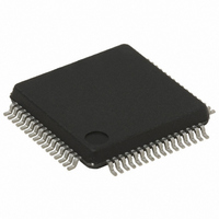
ST72F321BR9T6 STMicroelectronics, ST72F321BR9T6 Datasheet - Page 121

ST72F321BR9T6
Manufacturer Part Number
ST72F321BR9T6
Description
MCU 8BIT 60KB FLASH/ROM 64-LQFP
Manufacturer
STMicroelectronics
Series
ST7r
Datasheet
1.ST72F321BK6T6.pdf
(187 pages)
Specifications of ST72F321BR9T6
Core Processor
ST7
Core Size
8-Bit
Speed
8MHz
Connectivity
I²C, SCI, SPI
Peripherals
LVD, POR, PWM, WDT
Number Of I /o
48
Program Memory Size
60KB (60K x 8)
Program Memory Type
FLASH
Ram Size
2K x 8
Voltage - Supply (vcc/vdd)
3.8 V ~ 5.5 V
Data Converters
A/D 16x10b
Oscillator Type
Internal
Operating Temperature
-40°C ~ 85°C
Package / Case
64-LQFP
Processor Series
ST72F3x
Core
ST7
Data Bus Width
8 bit
Data Ram Size
2 KB
Interface Type
I2C, SCI, SPI
Maximum Clock Frequency
8 MHz
Number Of Programmable I/os
48
Number Of Timers
2
Maximum Operating Temperature
+ 85 C
Mounting Style
SMD/SMT
Development Tools By Supplier
ST7232X-EVAL, ST7232X-SK/RAIS, ST72321B-D/RAIS, ST7MDT20-DVP3, STX-RLINK
Minimum Operating Temperature
- 40 C
On-chip Adc
10 bit, 16 Channel
Cpu Family
ST7
Device Core Size
8b
Frequency (max)
8MHz
Total Internal Ram Size
2KB
# I/os (max)
48
Number Of Timers - General Purpose
2
Operating Supply Voltage (typ)
5V
Operating Supply Voltage (max)
5.5V
Operating Supply Voltage (min)
3.8V
Instruction Set Architecture
CISC
Operating Temp Range
-40C to 85C
Operating Temperature Classification
Industrial
Mounting
Surface Mount
Pin Count
64
Package Type
LQFP
For Use With
497-5046 - KIT TOOL FOR ST7/UPSD/STR7 MCU
Lead Free Status / RoHS Status
Lead free / RoHS Compliant
Eeprom Size
-
Lead Free Status / Rohs Status
Details
Other names
497-5586
Available stocks
Company
Part Number
Manufacturer
Quantity
Price
Company:
Part Number:
ST72F321BR9T6
Manufacturer:
STMicroelectronics
Quantity:
10 000
I
10.7.5 Low Power Modes
10.7.6 Interrupts
Figure 68. Event Flags and Interrupt Generation
Note: The I
the same interrupt vector (see Interrupts chapter).
They generate an interrupt if the corresponding
Enable Control Bit is set and the I-bit in the CC reg-
ister is reset (RIM instruction).
2
WAIT
HALT
10-bit Address Sent Event (Master mode)
End of Byte Transfer Event
Address Matched Event (Slave mode)
Start Bit Generation Event (Master mode)
Acknowledge Failure Event
Stop Detection Event (Slave mode)
Arbitration Lost Event (Multimaster configuration)
Bus Error Event
C BUS INTERFACE (Cont’d)
Mode
*
EVF can also be set by EV6 or an error from the SR2 register.
STOPF
ADD10
BERR
ARLO
ADSL
*
BTF
No effect on I
I
I
In HALT mode, the I
resumes operation when the MCU is woken up by an interrupt with “exit from HALT mode” capability.
2
2
SB
AF
2
C interrupts cause the device to exit from WAIT mode.
C registers are frozen.
C interrupt events are connected to
2
C interface.
Interrupt Event
2
C interface is inactive and does not acknowledge data on the bus. The I
ST72321BRx, ST72321BARx ST72321BJx, ST72321BKx
ITE
Description
ADSEL
STOPF
ADD10
BERR
Event
ARLO
Flag
BTF
SB
AF
Control
Enable
ITE
Bit
INTERRUPT
EVF
from
Wait
Exit
Yes
Yes
Yes
Yes
Yes
Yes
Yes
Yes
2
C interface
121/187
from
Halt
Exit
No
No
No
No
No
No
No
No


