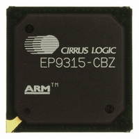
EP9315-CBZ Cirrus Logic Inc, EP9315-CBZ Datasheet - Page 56

EP9315-CBZ
Manufacturer Part Number
EP9315-CBZ
Description
IC ARM9 SOC ENH UNIV 352PBGA
Manufacturer
Cirrus Logic Inc
Series
EP9r
Specifications of EP9315-CBZ
Core Size
16/32-Bit
Core Processor
ARM9
Speed
200MHz
Connectivity
EBI/EMI, EIDE, Ethernet, I²C, IrDA, Keypad/Touchscreen, PCMCIA, SPI, UART/USART, USB
Peripherals
AC'97, DMA, I²:S, LCD, LED, MaverickKey, POR, PWM, WDT
Number Of I /o
16
Program Memory Type
ROMless
Ram Size
32K x 8
Voltage - Supply (vcc/vdd)
1.65 V ~ 3.6 V
Data Converters
A/D 8x12b
Oscillator Type
External
Operating Temperature
0°C ~ 70°C
Package / Case
352-BGA
Controller Family/series
(ARM9)
No. Of I/o's
16
Cpu Speed
200MHz
No. Of Timers
5
Digital Ic Case Style
BGA
Supply Voltage Range
1.65V To 1.94V, 3V To 3.6V
Embedded Interface Type
SPI
Rohs Compliant
Yes
Processor Series
EP93xx
Core
ARM920T
Data Bus Width
32 bit
3rd Party Development Tools
MDK-ARM, RL-ARM, ULINK2
Development Tools By Supplier
EDB9315A-Z
Case
BGA
Dc
06+
Lead Free Status / RoHS Status
Lead free / RoHS Compliant
For Use With
598-1144 - KIT DEVELOPMENT EP9315 ARM9
Eeprom Size
-
Program Memory Size
-
Lead Free Status / Rohs Status
Details
Other names
598-1139
Available stocks
Company
Part Number
Manufacturer
Quantity
Price
Part Number:
EP9315-CBZ
Manufacturer:
CIRRUS
Quantity:
20 000
EP9315
Enhanced Universal Platform SOC Processor
352 Pin BGA Pinout (Bottom View)
The following table shows the 352 pin BGA pinout. (For better understanding, compare the coordinates on the x and y
axis on
56
Note:
• VDD_core is CVDD.
• VDD_ring is RVDD.
• All core and ring grounds are connected together and are labelled GND.
• Other special power requirements are clearly labelled (i.e. H18=ADC_VDD and H19=ADC_GND).
• NC means that the pin is not connected.
Figure 40, "352 PIN BGA PINOUT", on page 57
1. Controlling Dimension: Millimeter.
2. Primary Datum C and seating plane are defined by the spherical crowns of the solder balls.
3. Dimension b is measured at the maximum solder ball diameter, parallel to Primary Datum C.
4. There shall be a minimum clearance of 0.25 mm between the edge of the solder ball and the body edge.
5. Reference Document: JEDEC MO-151, BAL-2
Symbol
ddd
A1
A2
D1
D2
D3
E1
E2
E3
A
D
E
b
c
e
q
26.80
23.80
17.95
26.80
23.80
17.95
MIN
2.20
1.12
0.51
-
-
-
-
-
-
Copyright 2010 Cirrus Logic (All Rights Reserved)
dimension in mm
Table R. 352 Pin Diagram Dimensions
30° TYP
NOM
27.00
24.13
24.00
18.00
27.00
24.13
24.00
18.00
2.30
0.60
1.17
0.75
0.56
1.27
-
with
27.20
24.20
18.05
27.20
24.20
18.05
MAX
2.50
1.22
0.61
0.15
-
-
-
-
-
Figure 40, "352 Pin PBGA Pin Diagram", on page
0.087
0.044
0.020
1.055
0.937
0.707
1.055
0.937
0.707
MIN
-
-
-
-
-
-
dimension in inches
30° TYP
NOM
0.092
0.024
0.046
0.030
0.022
1.063
0.950
0.945
0.709
1.063
0.950
0.945
0.709
0.050
-
MAX
0.098
0.048
0.024
1.071
0.953
1.071
0.953
0.006
0.711
0.711
-
-
-
-
-
DS638F2
55.


