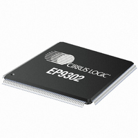
EP9302-CQZ Cirrus Logic Inc, EP9302-CQZ Datasheet - Page 8

EP9302-CQZ
Manufacturer Part Number
EP9302-CQZ
Description
IC ARM9 SOC PROCESSOR 208LQFP
Manufacturer
Cirrus Logic Inc
Series
EP9r
Datasheets
1.EP9307-CRZ.pdf
(824 pages)
2.EP9302-IQZ.pdf
(42 pages)
3.EP9302-IQZ.pdf
(4 pages)
4.EP9302-IQZ.pdf
(40 pages)
Specifications of EP9302-CQZ
Program Memory Type
ROMless
Package / Case
208-LQFP
Core Processor
ARM9
Core Size
16/32-Bit
Speed
200MHz
Connectivity
EBI/EMI, Ethernet, I²C, IrDA, SPI, UART/USART, USB
Peripherals
AC'97, DMA, I²:S, LED, MaverickKey, POR, PWM, WDT
Number Of I /o
19
Ram Size
32K x 8
Voltage - Supply (vcc/vdd)
1.65 V ~ 3.6 V
Data Converters
A/D 5x12b
Oscillator Type
External
Operating Temperature
0°C ~ 70°C
Processor Series
EP93xx
Core
ARM920T
Data Bus Width
32 bit
Data Ram Size
16 bit
Interface Type
USB, USART, SPI
Maximum Clock Frequency
200 MHz
Number Of Programmable I/os
37
Mounting Style
SMD/SMT
3rd Party Development Tools
MDK-ARM, RL-ARM, ULINK2
Development Tools By Supplier
EDB9302A-Z
Controller Family/series
(ARM9)
No. Of I/o's
19
Ram Memory Size
16MB
Cpu Speed
200MHz
No. Of Timers
4
Embedded Interface Type
AC97, I2S, SPI, UART, USB
Rohs Compliant
Yes
Lead Free Status / RoHS Status
Lead free / RoHS Compliant
For Use With
598-1132 - KIT DEVELOPMENT EP9302 ARM9
Eeprom Size
-
Program Memory Size
-
Lead Free Status / Rohs Status
Lead free / RoHS Compliant
Other names
598-1137
Available stocks
Company
Part Number
Manufacturer
Quantity
Price
Company:
Part Number:
EP9302-CQZ
Manufacturer:
Cirrus
Quantity:
3 295
Company:
Part Number:
EP9302-CQZ
Manufacturer:
ALTERA
Quantity:
672
Part Number:
EP9302-CQZ
Manufacturer:
CYPRESS/赛普拉斯
Quantity:
20 000
EP9302
High-speed ARM9 System-on-chip Processor with MaverickCrunch
Universal Asynchronous
Receiver/Transmitters (UARTs)
Two 16550-compatible UARTs are supplied. One
provides asynchronous HDLC (High-level Data Link
Control) protocol support for full duplex transmit and
receive. The HDLC receiver handles framing, address
matching, CRC checking, control-octet transparency, and
optionally passes the CRC to the host at the end of the
packet. The HDLC transmitter handles framing, CRC
generation, and control-octet transparency. The host
must
transmission. The HDLC receiver and transmitter use the
UART FIFOs to buffer the data streams. The second
UART provides IrDA
•
•
Dual-port USB Host
The USB Open Host Controller Interface (Open HCI)
provides full-speed serial communications ports at a
baud rate of 12 Mbits/sec. Up to 127 USB devices
(printer, mouse, camera, keyboard, etc.) and USB hubs
can be connected to the USB host in the USB “tiered-
star” topology.
This includes the following feature:
•
•
8
TXD0
RXD0
CTSn
DSRn / DCDn
DTRn
RTSn
EGPIO[0] / RI
TXD1 / SIROUT
RXD1 / SIRIN
Table F. Universal Asynchronous Receiver/Transmitters Pin
UART1 supports modem bit rates up to 115.2 kbps,
supports HDLC and includes a 16 byte FIFO for
receive and a 16 byte FIFO for transmit. Interrupts are
generated on Rx, Tx and modem status change.
UART2 contains an IrDA encoder operating at either
the slow (up to 115 kbps), medium (0.576 or 1.152
Mbps), or fast (4 Mbps) IR data rates. It also has a 16
byte FIFO for receive and a 16 byte FIFO for transmit.
Compliance with the USB 2.0 specification
Compliance with the Open HCI Rev 1.0 specification
Pin Mnemonic
assemble
the
®
compatibility.
UART1 Transmit
UART1 Receive
UART1 Clear To
Send / Transmit Enable
UART1 Data Set
Ready / Data Carrier Detect
UART1 Data Terminal Ready
UART1 Ready To Send
UART1 Ring Indicator
UART2 Transmit / IrDA
Output
UART2 Receive / IrDA Input
Assignments
frame
Pin Name - Description
in
Copyright 2010 Cirrus Logic (All Rights Reserved)
memory
before
•
•
•
•
•
The Open HCI host controller initializes the master DMA
transfer with the AHB bus:
•
•
•
•
Two-wire Interface
The two-wire interface provides communication and
control for synchronous-serial-driven devices.
Real-Time Clock with Software Trim
The software trim feature on the real time clock (RTC)
provides software controlled digital compensation of the
32.768 KHz input clock. This compensation is accurate to
±1.24 sec/month.
RTCXTALI
RTCXTALO
USBp[2,0]
USBm[2,0]
EECLK
EEDATA
Table H. Two-Wire Port with EEPROM Support Pin Assignments
Pin Mnemonic
Supports both low-speed (1.5 Mbps) and full-speed
(12 Mbps) USB device connections
Root HUB integrated with 2 downstream USB ports
Transceiver buffers integrated, over-current protection
on ports
Supports power management
Operates as a master on the bus
Fetches endpoint descriptors and transfer descriptors
Accesses endpoint data from system memory
Accesses the HC communication area
Writes status and retire transfer descriptor
Note:
Note:
Pin Mnemonic
Pin Mnemonic
Table I. Real-Time Clock with Pin Assignments
Table G. Dual Port USB Host Pin Assignments
USBm[1] and USBp[1] are not bonded out.
A real time clock must be connected to RTCXTALI or
the EP9302 device will not boot.
Two-wire Interface Clock
Two-Wire Interface Data
Pin Name - Description
USB Positive signals
USB Negative Signals
Real-Time Clock Oscillator Input
Real-Time Clock Oscillator Output
Pin Name - Description
Pin Name - Description
General
Purpose I/O
General
Purpose I/O
Alternative
Usage
DS653F2


