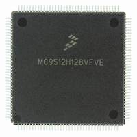
MC9S12H128VFVE Freescale Semiconductor, MC9S12H128VFVE Datasheet - Page 108

MC9S12H128VFVE
Manufacturer Part Number
MC9S12H128VFVE
Description
IC MCU 128K FLASH 16MHZ 144-LQFP
Manufacturer
Freescale Semiconductor
Series
HCS12r
Datasheet
1.MC9S12H256VFVER.pdf
(130 pages)
Specifications of MC9S12H128VFVE
Core Processor
HCS12
Core Size
16-Bit
Speed
16MHz
Connectivity
CAN, I²C, SCI, SPI
Peripherals
LCD, POR, PWM, WDT
Number Of I /o
99
Program Memory Size
128KB (128K x 8)
Program Memory Type
FLASH
Eeprom Size
4K x 8
Ram Size
6K x 8
Voltage - Supply (vcc/vdd)
2.35 V ~ 5.25 V
Data Converters
A/D 8x10b
Oscillator Type
Internal
Operating Temperature
-40°C ~ 105°C
Package / Case
144-LQFP
Processor Series
S12H
Core
HCS12
Data Bus Width
16 bit
Data Ram Size
6 KB
Interface Type
CAN/I2C/SCI/SPI
Maximum Clock Frequency
16 MHz
Number Of Programmable I/os
99
Number Of Timers
8
Operating Supply Voltage
- 0.3 V to + 6 V
Maximum Operating Temperature
+ 105 C
Mounting Style
SMD/SMT
3rd Party Development Tools
EWHCS12
Minimum Operating Temperature
- 40 C
On-chip Adc
16-ch x 10-bit
Package
144LQFP
Family Name
HCS12
Maximum Speed
16 MHz
Lead Free Status / RoHS Status
Lead free / RoHS Compliant
Available stocks
Company
Part Number
Manufacturer
Quantity
Price
Company:
Part Number:
MC9S12H128VFVE
Manufacturer:
Freescale Semiconductor
Quantity:
10 000
MC9S12H256 Device User Guide — V01.20
A.4.1.4 Stop Recovery
Out of STOP the controller can be woken up by an external interrupt. A clock quality check as after POR
is performed before releasing the clocks to the system.
A.4.1.5 Pseudo Stop and Wait Recovery
The recovery from Pseudo STOP and Wait are essentially the same since the oscillator was not stopped in
both modes. The controller can be woken up by internal or external interrupts. After t
fetching the interrupt vector.
A.4.2 Oscillator
The device features an internal Colpitts oscillator. By asserting the XCLKS input during reset this
oscillator can be bypassed allowing the input of a square wave. Before asserting the oscillator to the
internal system clocks the quality of the oscillation is checked for each start from either power-on, STOP
or oscillator fail. t
POR or STOP if a proper oscillation is not detected. The quality check also determines the minimum
oscillator start-up time t
asserted if the frequency of the incoming clock signal is below the Assert Frequency f
Conditions are shown in Table A-4 unless otherwise noted
Num C
NOTES:
1. f
2. Maximum value is for extreme cases using high Q, low frequency crystals
10
11
12
13
14
108
1
2
3
4
5
6
7
8
9
osc
C Crystal oscillator range
P Startup Current
D Oscillator start-up time from POR or STOP
C Oscillator start-up time
D Clock Quality check time-out
P Clock Monitor Failure Assert Frequency
P External square wave input frequency
D External square wave pulse width low
D External square wave pulse width high
D External square wave rise time
D External square wave fall time
D Input Capacitance EXTAL pin
D Input Capacitance XTAL pin
C
= 4MHz, C = 22pF.
DC Operating Bias in Colpitts Configuration on
EXTAL Pin
CQOUT
UPOSC
specifies the maximum time before switching to the internal self clock mode after
Rating
. The device also features a clock monitor. A Clock Monitor Failure is
Table A-14 Oscillator Characteristics
3
Symbol
V
n
t
t
UPOSC
CQOUT
f
t
t
UPOSC
t
t
DCBIAS
f
i
CMFA
EXTH
EXTR
f
EXTL
EXTF
OSC
OSC
C
C
EXT
IN
IN
4100
Min
0.45
100
0.5
0.5
50
15
15
Typ
100
1.1
13
8
9
1
wrs
CMFA.
the CPU starts
Max
100
200
2.5
16
32
1
1
2
cyc
Unit
MHz
MHz
KHz
ms
pF
pF
ns
ns
ns
ns
V
s
OSC
A


