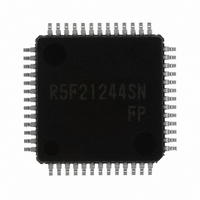
R5F21244SNFP#U0 Renesas Electronics America, R5F21244SNFP#U0 Datasheet - Page 519

R5F21244SNFP#U0
Manufacturer Part Number
R5F21244SNFP#U0
Description
IC R8C MCU FLASH 16K 52LQFP
Manufacturer
Renesas Electronics America
Series
M16C™ M16C/R8C/Tiny/24r
Datasheets
1.R5F211A2SPU0.pdf
(300 pages)
2.R5F21246SDFPU0.pdf
(61 pages)
3.R5F21246SDFPU0.pdf
(527 pages)
Specifications of R5F21244SNFP#U0
Core Processor
R8C
Core Size
16-Bit
Speed
20MHz
Connectivity
I²C, LIN, SIO, SSU, UART/USART
Peripherals
POR, Voltage Detect, WDT
Number Of I /o
41
Program Memory Size
16KB (16K x 8)
Program Memory Type
FLASH
Ram Size
1K x 8
Voltage - Supply (vcc/vdd)
2.2 V ~ 5.5 V
Data Converters
A/D 12x10b
Oscillator Type
Internal
Operating Temperature
-20°C ~ 85°C
Package / Case
52-LQFP
For Use With
R0K521256S000BE - KIT EVAL STARTER FOR R8C/25
Lead Free Status / RoHS Status
Lead free / RoHS Compliant
Eeprom Size
-
Available stocks
Company
Part Number
Manufacturer
Quantity
Price
Part Number:
R5F21244SNFP#U0R5F21244SNFP#V2
Manufacturer:
Renesas Electronics America
Quantity:
10 000
- Current page: 519 of 527
- Download datasheet (6Mb)
Rev.
1.00
REVISION HISTORY
May 31, 2006
Date
Page
415
416
420
421
422
423
424
425
426
427
434
438
442
445
448
450
451
452
456
462
463
466
19.7.1.7 Reset Flash Memory deleted
21.3.2 Notes on Timer RB;
21.3.3.1 TRDSTR Register (i = 0 or 1) revised
21.3.3.8 PWM3 Mode deleted
21.6 Notes on Hardware LIN; “Sync Break” → “Synch Break” revised
21.8.1.7 Reset Flash Memory deleted
Figure 19.17 Pin Connections for Standard Serial I/O Mode 3 title revised
Figure 19.18 Pin Processing in Standard Serial I/O Mode 2 added,
Figure 19.19 Pin Processing in Standard Serial I/O Mode 3 title revised
Table 20.2 Recommended Operating Conditions revised
Figure 20.1 Ports P0 to P4, P6 Timing Measurement Circuit; title revised
Table 20.4 Flash Memory (Program ROM) Electrical Characteristics
revised
Table 20.5 Flash Memory (Data flash Block A, Block B) Electrical
Characteristics revised
Figure 20.2 Time delay until Suspend title revised
Table 20.9 Voltage Monitor 0 Reset Electrical Characteristics → Table
20.9 Power-on Reset Circuit, Voltage Monitor 0 Reset Electrical
Characteristics revised
Table 20.10 Power-on Reset Circuit Electrical Characteristics (When Not
Using Voltage Monitor 0 Reset) deleted
Figure 20.3 Power-on Reset Circuit Electrical Characteristics revised
Table 20.10 High-speed On-Chip Oscillator Circuit Electrical
Characteristics revised
Table 20.11 Low-speed On-Chip Oscillator Circuit Electrical
Characteristics revised
Table 20.16 Electrical Characteristics (2) [Vcc = 5 V] revised
Table 20.22 Electrical Characteristics (4) [Vcc = 3 V] revised
Table 20.28 Electrical Characteristics (6) [Vcc = 2.2 V] revised
21.1.1 Stop Mode and Wait Mode revised and 21.1.4 fOCO40M deleted
21.2.7 Entering Wait Mode after Oscillation Stop Detection Interrupt is
Detected deleted
21.3.3.6 Reset Synchronous PWM Mode; Change procedure (2) revised
21.3.3.7 Complementary PWM Mode;
21.7 Notes on A/D Converter revised
R8C/24 Group, R8C/25 Group Hardware Manual
“ • ... Timer RB starts counting at the first ... 1 (during count).” deleted
“ • When the TSTOP bit in the TRBCR register ... immediately stops.
•Change bits CMD1 to CMD0 in the TRDFCR register in the ...;
•Do not write to ...; “However, set to the TRDGRD0, ... BFD1.” added
Change procedure: When stopping complementary ... (1) and (2) revised
• If the TOSST bit or the TOSSP bit ... also be set to 0 or 1.” added
Change procedure: When setting to complementary ... (2) ,
C - 15
Description
Summary
Related parts for R5F21244SNFP#U0
Image
Part Number
Description
Manufacturer
Datasheet
Request
R

Part Number:
Description:
KIT STARTER FOR M16C/29
Manufacturer:
Renesas Electronics America
Datasheet:

Part Number:
Description:
KIT STARTER FOR R8C/2D
Manufacturer:
Renesas Electronics America
Datasheet:

Part Number:
Description:
R0K33062P STARTER KIT
Manufacturer:
Renesas Electronics America
Datasheet:

Part Number:
Description:
KIT STARTER FOR R8C/23 E8A
Manufacturer:
Renesas Electronics America
Datasheet:

Part Number:
Description:
KIT STARTER FOR R8C/25
Manufacturer:
Renesas Electronics America
Datasheet:

Part Number:
Description:
KIT STARTER H8S2456 SHARPE DSPLY
Manufacturer:
Renesas Electronics America
Datasheet:

Part Number:
Description:
KIT STARTER FOR R8C38C
Manufacturer:
Renesas Electronics America
Datasheet:

Part Number:
Description:
KIT STARTER FOR R8C35C
Manufacturer:
Renesas Electronics America
Datasheet:

Part Number:
Description:
KIT STARTER FOR R8CL3AC+LCD APPS
Manufacturer:
Renesas Electronics America
Datasheet:

Part Number:
Description:
KIT STARTER FOR RX610
Manufacturer:
Renesas Electronics America
Datasheet:

Part Number:
Description:
KIT STARTER FOR R32C/118
Manufacturer:
Renesas Electronics America
Datasheet:

Part Number:
Description:
KIT DEV RSK-R8C/26-29
Manufacturer:
Renesas Electronics America
Datasheet:

Part Number:
Description:
KIT STARTER FOR SH7124
Manufacturer:
Renesas Electronics America
Datasheet:

Part Number:
Description:
KIT STARTER FOR H8SX/1622
Manufacturer:
Renesas Electronics America
Datasheet:

Part Number:
Description:
KIT DEV FOR SH7203
Manufacturer:
Renesas Electronics America
Datasheet:


