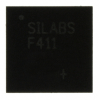
C8051F411-GM Silicon Laboratories Inc, C8051F411-GM Datasheet - Page 52

C8051F411-GM
Manufacturer Part Number
C8051F411-GM
Description
IC 8051 MCU 32K FLASH 28QFN
Manufacturer
Silicon Laboratories Inc
Series
C8051F41xr
Specifications of C8051F411-GM
Program Memory Type
FLASH
Program Memory Size
32KB (32K x 8)
Package / Case
28-QFN
Core Processor
8051
Core Size
8-Bit
Speed
50MHz
Connectivity
SMBus (2-Wire/I²C), SPI, UART/USART
Peripherals
Brown-out Detect/Reset, POR, PWM, Temp Sensor, WDT
Number Of I /o
20
Ram Size
2.25K x 8
Voltage - Supply (vcc/vdd)
2 V ~ 5.25 V
Data Converters
A/D 20x12b; D/A 2x12b
Oscillator Type
Internal
Operating Temperature
-40°C ~ 85°C
Processor Series
C8051F4x
Core
8051
Data Bus Width
8 bit
Data Ram Size
2368 B
Interface Type
I2C, SMBus, SPI, UART
Maximum Clock Frequency
50 MHz
Number Of Programmable I/os
20
Number Of Timers
4
Operating Supply Voltage
2 V to 5.25 V
Maximum Operating Temperature
+ 85 C
Mounting Style
SMD/SMT
3rd Party Development Tools
PK51, CA51, A51, ULINK2
Development Tools By Supplier
C8051F410DK
Minimum Operating Temperature
- 40 C
On-chip Adc
12 bit, 20 Channel
On-chip Dac
12 bit, 2 Channel
No. Of I/o's
20
Ram Memory Size
2368Byte
Cpu Speed
50MHz
No. Of Timers
4
Rohs Compliant
Yes
Lead Free Status / RoHS Status
Lead free / RoHS Compliant
For Use With
770-1006 - ISP 4PORT FOR SILABS C8051F MCU336-1454 - ADAPTER PROGRAM TOOLSTICK F411336-1317 - KIT EVAL FOR C8051F411336-1314 - KIT DEV FOR C8051F41X
Eeprom Size
-
Lead Free Status / Rohs Status
Lead free / RoHS Compliant
Other names
336-1309
Available stocks
Company
Part Number
Manufacturer
Quantity
Price
Company:
Part Number:
C8051F411-GM
Manufacturer:
Silicon
Quantity:
3
Part Number:
C8051F411-GM
Manufacturer:
SILICON LABS/芯科
Quantity:
20 000
Company:
Part Number:
C8051F411-GMR
Manufacturer:
SiliconL
Quantity:
3 000
Part Number:
C8051F411-GMR
Manufacturer:
SILICON LABS/芯科
Quantity:
20 000
C8051F410/1/2/3
5.2.
The typical temperature sensor transfer function is shown in Figure 5.2. The output voltage (V
positive ADC input when the temperature sensor is selected by bits AD0MX4-0 in register ADC0MX.
5.3.
In a typical system, ADC0 is configured using the following steps:
52
1.000
0.900
0.800
0.700
0.600
0.500
(Volts)
Temperature Sensor
ADC0 Operation
Step 1. Choose the start of conversion source.
Step 2. Choose Normal Mode or Burst Mode operation.
Step 3. If Burst Mode, choose the ADC0 Idle Power State and set the Power-Up Time.
Step 4. Choose the tracking mode. Note that Pre-Tracking Mode can only be used with Normal
Step 5. Calculate required settling time and set the post convert-start tracking time using the
Step 6. Choose the repeat count.
Step 7. Choose the output word justification (Right-Justified or Left-Justified).
Step 8. Enable or disable the End of Conversion and Window Comparator Interrupts.
Figure 5.2. Typical Temperature Sensor Transfer Function
Mode.
AD0TK bits.
-50
0
Rev. 1.1
V
TEMP
50
= SLOPE(TEMP
100
C
) + Offset
(Celsius)
TEMP
) is the


