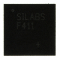
C8051F411-GM Silicon Laboratories Inc, C8051F411-GM Datasheet - Page 241

C8051F411-GM
Manufacturer Part Number
C8051F411-GM
Description
IC 8051 MCU 32K FLASH 28QFN
Manufacturer
Silicon Laboratories Inc
Series
C8051F41xr
Specifications of C8051F411-GM
Program Memory Type
FLASH
Program Memory Size
32KB (32K x 8)
Package / Case
28-QFN
Core Processor
8051
Core Size
8-Bit
Speed
50MHz
Connectivity
SMBus (2-Wire/I²C), SPI, UART/USART
Peripherals
Brown-out Detect/Reset, POR, PWM, Temp Sensor, WDT
Number Of I /o
20
Ram Size
2.25K x 8
Voltage - Supply (vcc/vdd)
2 V ~ 5.25 V
Data Converters
A/D 20x12b; D/A 2x12b
Oscillator Type
Internal
Operating Temperature
-40°C ~ 85°C
Processor Series
C8051F4x
Core
8051
Data Bus Width
8 bit
Data Ram Size
2368 B
Interface Type
I2C, SMBus, SPI, UART
Maximum Clock Frequency
50 MHz
Number Of Programmable I/os
20
Number Of Timers
4
Operating Supply Voltage
2 V to 5.25 V
Maximum Operating Temperature
+ 85 C
Mounting Style
SMD/SMT
3rd Party Development Tools
PK51, CA51, A51, ULINK2
Development Tools By Supplier
C8051F410DK
Minimum Operating Temperature
- 40 C
On-chip Adc
12 bit, 20 Channel
On-chip Dac
12 bit, 2 Channel
No. Of I/o's
20
Ram Memory Size
2368Byte
Cpu Speed
50MHz
No. Of Timers
4
Rohs Compliant
Yes
Lead Free Status / RoHS Status
Lead free / RoHS Compliant
For Use With
770-1006 - ISP 4PORT FOR SILABS C8051F MCU336-1454 - ADAPTER PROGRAM TOOLSTICK F411336-1317 - KIT EVAL FOR C8051F411336-1314 - KIT DEV FOR C8051F41X
Eeprom Size
-
Lead Free Status / Rohs Status
Lead free / RoHS Compliant
Other names
336-1309
Available stocks
Company
Part Number
Manufacturer
Quantity
Price
Company:
Part Number:
C8051F411-GM
Manufacturer:
Silicon
Quantity:
3
Part Number:
C8051F411-GM
Manufacturer:
SILICON LABS/芯科
Quantity:
20 000
Company:
Part Number:
C8051F411-GMR
Manufacturer:
SiliconL
Quantity:
3 000
Part Number:
C8051F411-GMR
Manufacturer:
SILICON LABS/芯科
Quantity:
20 000
24.2.3. External/smaRTClock Capture Mode
Capture Mode allows either the external oscillator or the smaRTClock clock to be measured against the
system clock. The external oscillator and smaRTClock clock can also be compared against each other.
Timer 2 can be clocked from the system clock, the system clock divided by 12, the external oscillator
divided by 8, or the smaRTClock clock divided by 8, depending on the T2ML (CKCON.4), T2XCLK, and
T2RCLK settings. The timer will capture either every 8 external clock cycles or every 8 smaRTClock clock
cycles, depending on the T2RCLK setting. When a capture event is generated, the contents of Timer 2
(TMR2H:TMR2L) are loaded into the Timer 2 reload registers (TMR2RLH:TMR2RLL) and the TF2H flag is
set. By recording the difference between two successive timer capture values, the external oscillator or
smaRTClock clock can be determined with respect to the Timer 2 clock. The Timer 2 clock should be much
faster than the capture clock to achieve an accurate reading. Timer 2 should be in 16-bit auto-reload mode
when using Capture Mode.
For example, if T2ML = 1b, T2RCLK = 0b, and TF2CEN = 1b, Timer 2 will clock every SYSCLK and cap-
ture every smaRTClock clock divided by 8. If the SYSCLK is 24.5 MHz and the difference between two
successive captures is 5984, then the smaRTClock clock is:
24.5 MHz / (5984 / 8) = 0.032754 MHz or 32.754 kHz.
This mode allows software to determine the exact smaRTClock frequency in self-oscillate mode and the
external oscillator frequency when an RC network or capacitor is used to generate the signal.
External Osc. / 8
smaRTClock / 8
T2RCLK
1
0
SYSCLK / 12
Figure 24.6. Timer 2 Capture Mode Block Diagram
T2XCLK
1
0
SYSCLK
External Osc. / 8
smaRTClock / 8
M
H
T
3
M
T
3
L
CKCON
M
T
2
H
TF2CEN
M
T
2
L
1
0
M
T
1
M
T
0
S
C
A
1
S
C
A
0
TR2
Rev. 1.1
T2RCLK
1
0
Capture
TCLK
TMR2RLH
TMR2H
TMR2RLL
TMR2L
C8051F410/1/2/3
TF2CEN
T2RCLK
TF2LEN
T2XCLK
TF2H
TF2L
TR2
Interrupt
241


