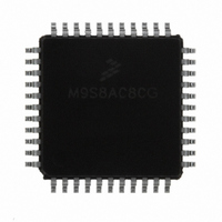
MC9S08AC8CFGE Freescale Semiconductor, MC9S08AC8CFGE Datasheet - Page 66

MC9S08AC8CFGE
Manufacturer Part Number
MC9S08AC8CFGE
Description
IC MCU 8BIT 8K FLASH 44-LQFP
Manufacturer
Freescale Semiconductor
Series
HCS08r
Datasheet
1.MC9S08AC8CFGE.pdf
(336 pages)
Specifications of MC9S08AC8CFGE
Core Processor
HCS08
Core Size
8-Bit
Speed
40MHz
Connectivity
I²C, SCI, SPI
Peripherals
LVD, POR, PWM, WDT
Number Of I /o
34
Program Memory Size
8KB (8K x 8)
Program Memory Type
FLASH
Ram Size
768 x 8
Voltage - Supply (vcc/vdd)
2.7 V ~ 5.5 V
Data Converters
A/D 8x10b
Oscillator Type
Internal
Operating Temperature
-40°C ~ 85°C
Package / Case
44-LQFP
Processor Series
S08AC
Core
HCS08
Data Bus Width
8 bit
Data Ram Size
700 B
Interface Type
I2C, SCI, SPI
Maximum Clock Frequency
40 MHz
Number Of Programmable I/os
34
Number Of Timers
3
Operating Supply Voltage
- 0.3 V to + 5.8 V
Maximum Operating Temperature
+ 125 C
Mounting Style
SMD/SMT
3rd Party Development Tools
EWS08
Development Tools By Supplier
DEMO9S08AC60E, DEMOACEX, DEMOACKIT, DCF51AC256, DC9S08AC128, DC9S08AC16, DC9S08AC60, DEMO51AC256KIT
Minimum Operating Temperature
- 40 C
On-chip Adc
10 bit, 8 Channel
Lead Free Status / RoHS Status
Lead free / RoHS Compliant
Eeprom Size
-
Lead Free Status / Rohs Status
Lead free / RoHS Compliant
Available stocks
Company
Part Number
Manufacturer
Quantity
Price
Company:
Part Number:
MC9S08AC8CFGE
Manufacturer:
Freescale Semiconductor
Quantity:
10 000
- Current page: 66 of 336
- Download datasheet (7Mb)
Chapter 5 Resets, Interrupts, and System Configuration
When two or more interrupts are pending when the I bit is cleared, the highest priority source is serviced
first (see
5.5.1
Figure 5-1
(SP) points at the next available byte location on the stack. The current values of CPU registers are stored
on the stack starting with the low-order byte of the program counter (PCL) and ending with the CCR. After
stacking, the SP points at the next available location on the stack which is the address that is one less than
the address where the CCR was saved. The PC value that is stacked is the address of the instruction in the
main program that would have executed next if the interrupt had not occurred.
When an RTI instruction is executed, these values are recovered from the stack in reverse order. As part
of the RTI sequence, the CPU fills the instruction pipeline by reading three bytes of program information,
starting from the PC address recovered from the stack.
The status flag causing the interrupt must be acknowledged (cleared) before returning from the ISR.
Typically, the flag should be cleared at the beginning of the ISR so that if another interrupt is generated by
this same source, it will be registered so it can be serviced after completion of the current ISR.
5.5.2
External interrupts are managed by the IRQ status and control register, IRQSC. When the IRQ function is
enabled, synchronous logic monitors the pin for edge-only or edge-and-level events. When the MCU is in
66
Table
shows the contents and organization of a stack frame. Before the interrupt, the stack pointer
Interrupt Stack Frame
External Interrupt Request (IRQ) Pin
For compatibility with the M68HC08, the H register is not automatically
saved and restored. It is good programming practice to push H onto the stack
at the start of the interrupt service routine (ISR) and restore it immediately
before the RTI that is used to return from the ISR.
5-2).
STACKING
ORDER
UNSTACKING
5
4
3
2
1
ORDER
1
2
3
4
5
* High byte (H) of index register is not automatically stacked.
7
INDEX REGISTER (LOW BYTE X)
MC9S08AC16 Series Data Sheet, Rev. 8
Figure 5-1. Interrupt Stack Frame
CONDITION CODE REGISTER
PROGRAM COUNTER HIGH
PROGRAM COUNTER LOW
ACCUMULATOR
²
²
²
NOTE
TOWARD HIGHER ADDRESSES
TOWARD LOWER ADDRESSES
*
0
SP AFTER
INTERRUPT STACKING
SP BEFORE
THE INTERRUPT
Freescale Semiconductor
Related parts for MC9S08AC8CFGE
Image
Part Number
Description
Manufacturer
Datasheet
Request
R
Part Number:
Description:
Manufacturer:
Freescale Semiconductor, Inc
Datasheet:
Part Number:
Description:
Manufacturer:
Freescale Semiconductor, Inc
Datasheet:
Part Number:
Description:
Manufacturer:
Freescale Semiconductor, Inc
Datasheet:
Part Number:
Description:
Manufacturer:
Freescale Semiconductor, Inc
Datasheet:
Part Number:
Description:
Manufacturer:
Freescale Semiconductor, Inc
Datasheet:
Part Number:
Description:
Manufacturer:
Freescale Semiconductor, Inc
Datasheet:
Part Number:
Description:
Manufacturer:
Freescale Semiconductor, Inc
Datasheet:
Part Number:
Description:
Manufacturer:
Freescale Semiconductor, Inc
Datasheet:
Part Number:
Description:
Manufacturer:
Freescale Semiconductor, Inc
Datasheet:
Part Number:
Description:
Manufacturer:
Freescale Semiconductor, Inc
Datasheet:
Part Number:
Description:
Manufacturer:
Freescale Semiconductor, Inc
Datasheet:
Part Number:
Description:
Manufacturer:
Freescale Semiconductor, Inc
Datasheet:
Part Number:
Description:
Manufacturer:
Freescale Semiconductor, Inc
Datasheet:
Part Number:
Description:
Manufacturer:
Freescale Semiconductor, Inc
Datasheet:
Part Number:
Description:
Manufacturer:
Freescale Semiconductor, Inc
Datasheet:


