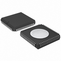
P87C554SFAA,512 NXP Semiconductors, P87C554SFAA,512 Datasheet - Page 49

P87C554SFAA,512
Manufacturer Part Number
P87C554SFAA,512
Description
IC 80C51 MCU 16K OTP 64-PLCC
Manufacturer
NXP Semiconductors
Series
87Cr
Specifications of P87C554SFAA,512
Core Processor
8051
Core Size
8-Bit
Speed
16MHz
Connectivity
EBI/EMI, I²C, UART/USART
Peripherals
POR, PWM, WDT
Number Of I /o
40
Program Memory Size
16KB (16K x 8)
Program Memory Type
OTP
Ram Size
512 x 8
Voltage - Supply (vcc/vdd)
2.7 V ~ 5.5 V
Data Converters
A/D 8x10b
Oscillator Type
Internal
Operating Temperature
-40°C ~ 85°C
Package / Case
68-PLCC
Cpu Family
87C
Device Core
80C51
Device Core Size
8b
Frequency (max)
16MHz
Interface Type
I2C/UART
Total Internal Ram Size
512Byte
# I/os (max)
40
Number Of Timers - General Purpose
3
Operating Supply Voltage (typ)
5V
Operating Supply Voltage (max)
5.5V
Operating Supply Voltage (min)
4.5V
On-chip Adc
7-chx10-bit
Instruction Set Architecture
CISC
Operating Temp Range
-40C to 85C
Operating Temperature Classification
Industrial
Mounting
Surface Mount
Pin Count
68
Package Type
PLCC
Processor Series
P87C5x
Core
80C51
Data Bus Width
8 bit
Data Ram Size
512 B
Maximum Clock Frequency
16 MHz
Number Of Programmable I/os
40
Number Of Timers
3
Operating Supply Voltage
2.7 V to 5.5 V
Maximum Operating Temperature
+ 85 C
Mounting Style
SMD/SMT
3rd Party Development Tools
PK51, CA51, A51, ULINK2
Minimum Operating Temperature
- 40 C
Package
68PLCC
Family Name
87C
Maximum Speed
16 MHz
Lead Free Status / RoHS Status
Lead free / RoHS Compliant
Eeprom Size
-
Lead Free Status / Rohs Status
Compliant
Other names
568-1255-5
935263922512
P87C554SFAA
935263922512
P87C554SFAA
Available stocks
Company
Part Number
Manufacturer
Quantity
Price
Company:
Part Number:
P87C554SFAA,512
Manufacturer:
Maxim
Quantity:
145
Company:
Part Number:
P87C554SFAA,512
Manufacturer:
NXP Semiconductors
Quantity:
10 000
Philips Semiconductors
I
An I
uncontrolled source. If the SCL line is obstructed (pulled LOW) by a
device on the bus, no further serial transfer is possible, and the
SIO1 hardware cannot resolve this type of problem. When this
occurs, the problem must be resolved by the device that is pulling
the SCL bus line LOW.
If the SDA line is obstructed by another device on the bus (e.g., a
slave device out of bit synchronization), the problem can be solved
by transmitting additional clock pulses on the SCL line (see Figure
46). The SIO1 hardware transmits additional clock pulses when the
STA flag is set, but no START condition can be generated because
the SDA line is pulled LOW while the I
The SIO1 hardware attempts to generate a START condition after
every two additional clock pulses on the SCL line. When the SDA
line is eventually released, a normal START condition is transmitted,
state 08H is entered, and the serial transfer continues.
If a forced bus access occurs or a repeated START condition is
transmitted while SDA is obstructed (pulled LOW), the SIO1
2003 Jan 28
2
C B
80C51 8-bit microcontroller – 6-clock operation
16K/512 OTP/ROMless, 7 channel 10 bit A/D, I
high I/O, 64L LQFP
2
C bus hang-up occurs if SDA or SCL is pulled LOW by an
US
O
BSTRUCTED BY A
08H
S
STA FLAG
SDA LINE
SCL LINE
SLA
L
OW
L
W
EVEL ON
Figure 44. Simultaneous Repeated START Conditions from 2 Masters
18H
2
A
C bus is considered free.
SCL
TIME OUT
OR
Figure 45. Forced Access to a Busy I
SDA
DATA
OTHER MASTER SENDS REPEATED
START CONDITION EARLIER
28H
A
2
C, PWM, capture/compare,
49
S
hardware performs the same action as described above. In each
case, state 08H is entered after a successful START condition is
transmitted and normal serial transfer continues. Note that the CPU
is not involved in solving these bus hang-up problems.
B
A bus error occurs when a START or STOP condition is present at
an illegal position in the format frame. Examples of illegal positions
are during the serial transfer of an address byte, a data or an
acknowledge bit.
The SIO1 hardware only reacts to a bus error when it is involved in
a serial transfer either as a master or an addressed slave. When a
bus error is detected, SIO1 immediately switches to the not
addressed slave mode, releases the SDA and SCL lines, sets the
interrupt flag, and loads the status register with 00H. This status
code may be used to vector to a service routine which either
attempts the aborted serial transfer again or simply recovers from
the error condition as shown in Table 10.
US
E
START CONDITION
BOTH MASTERS CONTINUE
WITH SLA TRANSMISSION
RROR
2
C Bus
80C554/87C554
SU00975
SU00976
Product data


