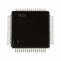
P80C554SFBD,157 NXP Semiconductors, P80C554SFBD,157 Datasheet - Page 13

P80C554SFBD,157
Manufacturer Part Number
P80C554SFBD,157
Description
IC 80C51 MCU 8BIT ROMLESS 64LQFP
Manufacturer
NXP Semiconductors
Series
80Cr
Datasheet
1.P80C554SFBD157.pdf
(76 pages)
Specifications of P80C554SFBD,157
Core Processor
8051
Core Size
8-Bit
Speed
16MHz
Connectivity
EBI/EMI, I²C, UART/USART
Peripherals
POR, PWM, WDT
Number Of I /o
40
Program Memory Type
ROMless
Ram Size
512 x 8
Voltage - Supply (vcc/vdd)
2.7 V ~ 5.5 V
Data Converters
A/D 7x10b
Oscillator Type
Internal
Operating Temperature
-40°C ~ 85°C
Package / Case
64-LQFP
Processor Series
P80C5x
Core
80C51
Data Bus Width
8 bit
Data Ram Size
512 B
Interface Type
I2C, UART
Maximum Clock Frequency
8 MHz, 16 MHz
Number Of Programmable I/os
40
Number Of Timers
3
Operating Supply Voltage
2.7 V to 5.5 V
Maximum Operating Temperature
+ 85 C
Mounting Style
SMD/SMT
3rd Party Development Tools
PK51, CA51, A51, ULINK2
Minimum Operating Temperature
- 40 C
On-chip Adc
10 bit, 7 Channel
Lead Free Status / RoHS Status
Lead free / RoHS Compliant
Eeprom Size
-
Program Memory Size
-
Lead Free Status / Rohs Status
Details
Other names
568-2086
935268881157
P80C554SFBD
935268881157
P80C554SFBD
Available stocks
Company
Part Number
Manufacturer
Quantity
Price
Company:
Part Number:
P80C554SFBD,157
Manufacturer:
NXP Semiconductors
Quantity:
10 000
Philips Semiconductors
2003 Jan 28
80C51 8-bit microcontroller – 6-clock operation
16K/512 OTP/ROMless, 7 channel 10 bit A/D, I
high I/O, 64L LQFP
NOTE:
*User software should not write 1s to reserved bits. These bits may be used in future 8051 family products to invoke new features. In that
case, the reset or inactive value of the new bit will be 0, and its active value will be 1. The value read from a reserved bit is indeterminate.
AUXR1
Symbol
DPS
WUPD
GF2
SRST
AIDL
ADC8
Address = A2H
Not Bit Addressable
Bit:
Function
Data Pointer Switch—switches between DPRT0 and DPTR1.
DPS
0
1
Enable wakeup from powerdown.
General Purpose Flag—set and cleared by the user.
Software Reset
Enables the ADC during idle mode.
ADC Mode Switch—switches between 10-bit conversion and 8-bit conversion.
ADC8
0
1
ADC8
7
Operating Mode
DPTR0
DPTR1
Operating Mode
10-bit conversion (50 machine cycles)
8-bit conversion (24 machine cycles)
AIDL
6
SRST
Figure 7. AUXR1: DPTR Control Register
5
GF2
4
2
C, PWM, capture/compare,
WUPD
13
3
0
2
—
1
DSP
0
Reset Value = 0000 00x0B
80C554/87C554
Product data
SU01081


