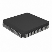
PIC17C752-16/L Microchip Technology, PIC17C752-16/L Datasheet - Page 151

PIC17C752-16/L
Manufacturer Part Number
PIC17C752-16/L
Description
IC MCU OTP 8KX16 A/D PWM 68PLCC
Manufacturer
Microchip Technology
Series
PIC® 17Cr
Datasheets
1.PIC16F616T-ISL.pdf
(8 pages)
2.PIC17C752-16L.pdf
(304 pages)
3.PIC17C752-16L.pdf
(4 pages)
4.PIC17C752-16L.pdf
(6 pages)
Specifications of PIC17C752-16/L
Core Size
8-Bit
Program Memory Size
16KB (8K x 16)
Peripherals
Brown-out Detect/Reset, POR, PWM, WDT
Core Processor
PIC
Speed
16MHz
Connectivity
I²C, SPI, UART/USART
Number Of I /o
50
Program Memory Type
OTP
Ram Size
454 x 8
Voltage - Supply (vcc/vdd)
4.5 V ~ 5.5 V
Data Converters
A/D 12x10b
Oscillator Type
External
Operating Temperature
0°C ~ 70°C
Package / Case
68-PLCC
Controller Family/series
PIC17
No. Of I/o's
50
Ram Memory Size
678Byte
Cpu Speed
16MHz
No. Of Timers
4
Processor Series
PIC17C
Core
PIC
Data Bus Width
8 bit
Data Ram Size
678 B
Interface Type
I2C, MSSP, RS- 232, SCI, SPI, USART
Maximum Clock Frequency
33 MHz
Number Of Programmable I/os
50
Number Of Timers
8
Operating Supply Voltage
3 V to 5.5 V
Maximum Operating Temperature
+ 70 C
Mounting Style
SMD/SMT
Development Tools By Supplier
ICE2000, DM173001
Minimum Operating Temperature
0 C
On-chip Adc
12 bit
Lead Free Status / RoHS Status
Lead free / RoHS Compliant
For Use With
AC164308 - MODULE SKT FOR PM3 68PLCCDVA17XL681 - DEVICE ADAPTER FOR PIC17C752DM173001 - KIT DEVELOPMENT PICDEM17AC174007 - MODULE SKT PROMATEII 68PLCCAC164024 - ADAPTER PICSTART PLUS 68PLCC
Eeprom Size
-
Lead Free Status / Rohs Status
Details
Available stocks
Company
Part Number
Manufacturer
Quantity
Price
Company:
Part Number:
PIC17C752-16/L
Manufacturer:
Microchip
Quantity:
120
Company:
Part Number:
PIC17C752-16/L
Manufacturer:
Microchip Technology
Quantity:
10 000
- PIC16F616T-ISL PDF datasheet
- PIC17C752-16L PDF datasheet #2
- PIC17C752-16L PDF datasheet #3
- PIC17C752-16L PDF datasheet #4
- Current page: 151 of 304
- Download datasheet (6Mb)
15.2.5
Master mode of operation is supported by interrupt
generation on the detection of the START and STOP
conditions. The STOP (P) and START (S) bits are
cleared from a RESET, or when the MSSP module is
disabled. Control of the I
P bit is set, or the bus is idle, with both the S and P bits
clear.
In Master mode, the SCL and SDA lines are manipu-
lated by the MSSP hardware.
FIGURE 15-17:
2000 Microchip Technology Inc.
SDA
SCL
MASTER MODE
SSP BLOCK DIAGRAM (I
2
C bus may be taken when the
SDA In
Bus Collision
SCL In
Read
Write Collision Detect
MSb
START bit, STOP bit,
START bit Detect,
end of XMIT/RCV
State Counter for
Clock Arbitration
STOP bit Detect
Acknowledge
SSPBUF
Generate
SSPSR
2
C MASTER MODE)
LSb
Write
The following events will cause SSP Interrupt Flag bit,
SSPIF, to be set (SSP Interrupt if enabled):
• START condition
• STOP condition
• Data transfer byte transmitted/received
• Acknowledge transmit
• Repeated Start
Clock
Data Bus
Shift
Internal
Set/Reset, S, P, WCOL (SSPSTAT)
Set SSPIF, BCLIF
Reset ACKSTAT, PEN (SSPCON2)
PIC17C7XX
SSPADD<6:0>
SSPM3:SSPM0
Baud
Rate
Generator
DS30289B-page 151
Related parts for PIC17C752-16/L
Image
Part Number
Description
Manufacturer
Datasheet
Request
R

Part Number:
Description:
IC MCU OTP 8KX16 A/D PWM 68PLCC
Manufacturer:
Microchip Technology
Datasheet:

Part Number:
Description:
High-Performance 8-Bit CMOS EPROM Microcontrollers
Manufacturer:
MICROCHIP [Microchip Technology]
Datasheet:

Part Number:
Description:
High-Performance 8-Bit CMOS EPROM Microcontrollers with 10-bit A/D
Manufacturer:
MICROCHIP [Microchip Technology]
Datasheet:

Part Number:
Description:
IC MCU OTP 8KX16 A/D PWM 68PLCC
Manufacturer:
Microchip Technology
Datasheet:

Part Number:
Description:
IC MCU OTP 8KX16 A/D PWM 64TQFP
Manufacturer:
Microchip Technology
Datasheet:

Part Number:
Description:
IC MCU OTP 8KX16 A/D PWM 64TQFP
Manufacturer:
Microchip Technology
Datasheet:

Part Number:
Description:
IC MCU OTP 8KX16 A/D PWM 64TQFP
Manufacturer:
Microchip Technology
Datasheet:

Part Number:
Description:
IC MCU OTP 8KX16 A/D PWM 64TQFP
Manufacturer:
Microchip Technology
Datasheet:

Part Number:
Description:
IC MCU OTP 8KX16 A/D PWM 68PLCC
Manufacturer:
Microchip Technology
Datasheet:

Part Number:
Description:
IC MCU CMOS 33MHZ 8K EPRM 68PLCC
Manufacturer:
Microchip Technology
Datasheet:

Part Number:
Description:
IC MCU CMOS 16MHZ 8K EPRM 68PLCC
Manufacturer:
Microchip Technology
Datasheet:

Part Number:
Description:
IC MCU CMOS 16MHZ 8K EPRM 64TQFP
Manufacturer:
Microchip Technology
Datasheet:

Part Number:
Description:
IC MCU CMOS 33MHZ 8K EPRM 64TQFP
Manufacturer:
Microchip Technology
Datasheet:


