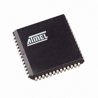
AT89C51CC03C-S3RIM Atmel, AT89C51CC03C-S3RIM Datasheet - Page 92

AT89C51CC03C-S3RIM
Manufacturer Part Number
AT89C51CC03C-S3RIM
Description
IC 8051 MCU FLASH 64K 52PLCC
Manufacturer
Atmel
Series
AT89C CANr
Datasheets
1.AT89C51CC03C-S3RIM.pdf
(198 pages)
2.AT89C51CC03C-S3RIM.pdf
(32 pages)
3.AT89C51CC03C-S3RIM.pdf
(27 pages)
4.AT89C51CC03C-S3RIM.pdf
(184 pages)
Specifications of AT89C51CC03C-S3RIM
Core Processor
8051
Core Size
8-Bit
Speed
40MHz
Connectivity
CAN, SPI, UART/USART
Peripherals
POR, PWM, WDT
Number Of I /o
36
Program Memory Size
64KB (64K x 8)
Program Memory Type
FLASH
Eeprom Size
2K x 8
Ram Size
2.25K x 8
Voltage - Supply (vcc/vdd)
3 V ~ 5.5 V
Data Converters
A/D 8x10b
Oscillator Type
External
Operating Temperature
-40°C ~ 85°C
Package / Case
52-PLCC
Lead Free Status / RoHS Status
Contains lead / RoHS non-compliant
Other names
AT89C51CC03CS3RTR
Available stocks
Company
Part Number
Manufacturer
Quantity
Price
- AT89C51CC03C-S3RIM PDF datasheet
- AT89C51CC03C-S3RIM PDF datasheet #2
- AT89C51CC03C-S3RIM PDF datasheet #3
- AT89C51CC03C-S3RIM PDF datasheet #4
- Current page: 92 of 198
- Download datasheet (3Mb)
Working on Message Objects
CAN Controller
Management
92
AT89C51CC03
The Page message object register (CANPAGE) is used to select one of the 15 message
objects. Then, message object Control (CANCONCH) and message object Status
(CANSTCH) are available for this selected message object number in the corresponding
SFRs. A single register (CANMSG) is used for the message. The mailbox pointer is
managed by the Page message object register with an auto-incrementation at the end of
each access. The range of this counter is 8.
Note that the maibox is a pure RAM, dedicated to one message object, without overlap.
In most cases, it is not necessary to transfer the received message into the standard
memory. The message to be transmitted can be built directly in the maibox. Most calcu-
lations or tests can be executed in the mailbox area which provide quicker access.
In order to enable the CAN Controller correctly the following registers have to be
initialized:
•
•
•
During operation, the CAN Enable message object registers 1 and 2 (CANEN 1 and 2)
gives a fast overview of the message objects availability.
The CAN messages can be handled by interrupt or polling modes.
A message object can be configured as follows:
•
•
•
•
This configuration is made in the CONCH1:2 field of the CANCONCH register (see
Table 46).
When a message object is configured, the corresponding ENCH bit of CANEN 1 and 2
register is set.
Table 46. Configuration for CONCH1:2
When a Transmitter or Receiver action of a message object is completed, the corre-
sponding ENCH bit of the CANEN 1 and 2 register is cleared. In order to re-enable the
message object, it is necessary to re-write the configuration in CANCONCH register.
Non-consecutive message objects can be used for all three types of message objects
(Transmitter, Receiver and Receiver buffer),
CONCH 1
General Control (CANGCON),
Bit Timing (CANBT 1, 2 and 3),
And for each page of 15 message objects
–
–
Transmit message object,
Receive message object,
Receive buffer message object.
Disable
0
0
1
1
message object Control (CANCONCH),
message object Status (CANSTCH).
CONCH 2
0
1
0
1
Type of Message Object
Disable
Transmitter
Receiver
Receiver buffer
4182O–CAN–09/08
Related parts for AT89C51CC03C-S3RIM
Image
Part Number
Description
Manufacturer
Datasheet
Request
R

Part Number:
Description:
Manufacturer:
Atmel Corporation
Datasheet:

Part Number:
Description:
At89c51cc03 Enhanced 8-bit Mcu With Can Controller And Flash Memory
Manufacturer:
ATMEL Corporation
Datasheet:

Part Number:
Description:
DEV KIT FOR AVR/AVR32
Manufacturer:
Atmel
Datasheet:

Part Number:
Description:
INTERVAL AND WIPE/WASH WIPER CONTROL IC WITH DELAY
Manufacturer:
ATMEL Corporation
Datasheet:

Part Number:
Description:
Low-Voltage Voice-Switched IC for Hands-Free Operation
Manufacturer:
ATMEL Corporation
Datasheet:

Part Number:
Description:
MONOLITHIC INTEGRATED FEATUREPHONE CIRCUIT
Manufacturer:
ATMEL Corporation
Datasheet:

Part Number:
Description:
AM-FM Receiver IC U4255BM-M
Manufacturer:
ATMEL Corporation
Datasheet:

Part Number:
Description:
Monolithic Integrated Feature Phone Circuit
Manufacturer:
ATMEL Corporation
Datasheet:

Part Number:
Description:
Multistandard Video-IF and Quasi Parallel Sound Processing
Manufacturer:
ATMEL Corporation
Datasheet:

Part Number:
Description:
High-performance EE PLD
Manufacturer:
ATMEL Corporation
Datasheet:

Part Number:
Description:
8-bit Flash Microcontroller
Manufacturer:
ATMEL Corporation
Datasheet:

Part Number:
Description:
2-Wire Serial EEPROM
Manufacturer:
ATMEL Corporation
Datasheet:


