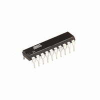
ATTINY2313V-10PU Atmel, ATTINY2313V-10PU Datasheet - Page 17

ATTINY2313V-10PU
Manufacturer Part Number
ATTINY2313V-10PU
Description
IC MCU AVR 2K FLASH 20DIP
Manufacturer
Atmel
Series
AVR® ATtinyr
Datasheets
1.ATTINY2313-20MU.pdf
(226 pages)
2.ATTINY2313V-10MU.pdf
(15 pages)
3.ATTINY2313V-10SU.pdf
(20 pages)
Specifications of ATTINY2313V-10PU
Core Processor
AVR
Core Size
8-Bit
Speed
10MHz
Connectivity
SPI, UART/USART
Peripherals
Brown-out Detect/Reset, POR, PWM, WDT
Number Of I /o
18
Program Memory Size
2KB (1K x 16)
Program Memory Type
FLASH
Eeprom Size
128 x 8
Ram Size
128 x 8
Voltage - Supply (vcc/vdd)
1.8 V ~ 5.5 V
Oscillator Type
Internal
Operating Temperature
-40°C ~ 85°C
Package / Case
20-DIP (0.300", 7.62mm)
Processor Series
ATTINY2x
Core
AVR8
Data Bus Width
8 bit
Data Ram Size
128 B
Interface Type
SPI/UART/USI
Maximum Clock Frequency
10 MHz
Number Of Programmable I/os
18
Number Of Timers
2
Operating Supply Voltage
1.8 V to 5.5 V
Maximum Operating Temperature
+ 85 C
Mounting Style
Through Hole
Minimum Operating Temperature
- 40 C
Package
20PDIP
Device Core
AVR
Family Name
ATtiny
Maximum Speed
10 MHz
Data Rom Size
128 B
Height
4.95 mm
Length
26.92 mm
Supply Voltage (max)
5.5 V
Supply Voltage (min)
1.8 V
Width
7.11 mm
For Use With
ATSTK600-DIP40 - STK600 SOCKET/ADAPTER 40-PDIP770-1007 - ISP 4PORT ATMEL AVR MCU SPI/JTAGATAVRDRAGON - KIT DRAGON 32KB FLASH MEM AVRATAVRISP2 - PROGRAMMER AVR IN SYSTEMATJTAGICE2 - AVR ON-CHIP D-BUG SYSTEM
Lead Free Status / RoHS Status
Lead free / RoHS Compliant
Data Converters
-
Lead Free Status / Rohs Status
Lead free / RoHS Compliant
Available stocks
Company
Part Number
Manufacturer
Quantity
Price
Company:
Part Number:
ATTINY2313V-10PU
Manufacturer:
ATMEL
Quantity:
3 000
Part Number:
ATTINY2313V-10PU
Manufacturer:
ATMEL/爱特梅尔
Quantity:
20 000
The EEPROM Data
Register – EEDR
The EEPROM Control
Register – EECR
2543L–AVR–08/10
• Bits 6..0 – EEAR6..0: EEPROM Address
The EEPROM Address Register – EEAR specify the EEPROM address in the 128 bytes
EEPROM space. The EEPROM data bytes are addressed linearly between 0 and 127. The ini-
tial value of EEAR is undefined. A proper value must be written before the EEPROM may be
accessed.
• Bits 7..0 – EEDR7..0: EEPROM Data
For the EEPROM write operation, the EEDR Register contains the data to be written to the
EEPROM in the address given by the EEAR Register. For the EEPROM read operation, the
EEDR contains the data read out from the EEPROM at the address given by EEAR.
• Bits 7..6 – Res: Reserved Bits
These bits are reserved bits in the ATtiny2313 and will always read as zero.
• Bits 5, 4 – EEPM1 and EEPM0: EEPROM Programming Mode Bits
The EEPROM Programming mode bits setting defines which programming action that will be
triggered when writing EEPE. It is possible to program data in one atomic operation (erase the
old value and program the new value) or to split the Erase and Write operations in two different
operations. The Programming times for the different modes are shown in
set, any write to EEPMn will be ignored. During reset, the EEPMn bits will be reset to 0b00
unless the EEPROM is busy programming.
Table 1. EEPROM Mode Bits
• Bit 3 – EERIE: EEPROM Ready Interrupt Enable
Writing EERIE to one enables the EEPROM Ready Interrupt if the I-bit in SREG is set. Writing
EERIE to zero disables the interrupt. The EEPROM Ready Interrupt generates a constant inter-
rupt when Non-volatile memory is ready for programming.
Bit
Read/Write
Initial Value
Bit
Read/Write
Initial Value
EEPM1
0
0
1
1
EEPM0
0
1
0
1
MSB
R/W
R
7
0
7
–
0
Programming
R/W
R
6
0
6
–
0
3.4 ms
1.8 ms
1.8 ms
Time
–
EEPM1
R/W
R/W
5
0
5
X
Operation
Erase and Write in one operation (Atomic Operation)
Erase Only
Write Only
Reserved for future use
EEPM0
R/W
R/W
4
0
4
X
EERIE
R/W
R/W
3
0
3
0
EEMPE
R/W
R/W
2
0
2
0
EEPE
R/W
R/W
1
0
1
X
EERE
LSB
R/W
R/W
Table
0
0
0
0
1. While EEPE is
EEDR
EECR
17


