ESDALC6V1-1BM2 STMicroelectronics, ESDALC6V1-1BM2 Datasheet - Page 8
ESDALC6V1-1BM2
Manufacturer Part Number
ESDALC6V1-1BM2
Description
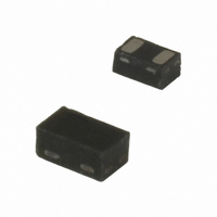
TRANSIL ARRAY ESD PROT SOD882
Manufacturer
STMicroelectronics
Series
TRANSIL™r
Specifications of ESDALC6V1-1BM2
Voltage - Reverse Standoff (typ)
3V
Voltage - Breakdown
6.1V
Power (watts)
140W
Polarization
Bidirectional
Mounting Type
Surface Mount
Package / Case
SOD-882
Number Of Elements
1
Polarity
Bi-Directional
Package Type
SOD-882
Operating Temperature Classification
Automotive
Reverse Breakdown Voltage
6.1V
Reverse Stand-off Voltage
3V
Leakage Current (max)
100nA
Peak Pulse Current
9A
Peak Pulse Power Dissipation
140W
Test Current (it)
1mA
Operating Temp Range
-40C to 125C
Mounting
Surface Mount
Pin Count
2
Lead Free Status / RoHS Status
Lead free / RoHS Compliant
Other names
497-5543-2
Available stocks
Company
Part Number
Manufacturer
Quantity
Price
Company:

Part Number:
ESDALC6V1-1BM2
Manufacturer:
STMicroelectronics
Quantity:
135
Part Number:
ESDALC6V1-1BM2
Manufacturer:
ST
Quantity:
20 000


Recommendation on PCB assembly
4.3
4.4
4.5
Note:
8/10
Placement
1.
2.
3.
4.
5.
6.
PCB design preference
1.
2.
Reflow profile
Figure 16. ST ECOPACK recommended soldering reflow profile for PCB mounting
Minimize air convection currents in the reflow oven to avoid component movement.
Manual positioning is not recommended.
It is recommended to use the lead recognition capabilities of the placement system, not
the outline centering
Standard tolerance of ± 0.05 mm is recommended.
3.5 N placement force is recommended. Too much placement force can lead to
squeezed out solder paste and cause solder joints to short. Too low placement force
can lead to insufficient contact between package and solder paste that could cause
open solder joints or badly centered packages.
To improve the package placement accuracy, a bottom side optical control should be
performed with a high resolution tool.
For assembly, a perfect supporting of the PCB (all the more on flexible PCB) is
recommended during solder paste printing, pick and place and reflow soldering by
using optimized tools.
To control the solder paste amount, the closed via is recommended instead of open
vias.
The position of tracks and open vias in the solder area should be well balanced. The
symmetrical layout is recommended, in case any tilt phenomena caused by
asymmetrical solder paste amount due to the solder flow away.
Temperature (°C)
Temperature (°C)
260°C max
260°C max
255°C
255°C
125 °C
125 °C
220°C
220°C
180°C
180°C
0
0
0
0
3°C/s max
3°C/s max
1
1
90 to 150 sec
90 to 150 sec
2
2
3
3
4
4
90 sec max
90 sec max
10-30 sec
10-30 sec
5
5
2°C/s recommended
6
6
6°C/s max
2°C/s recommended
ESDALC6V1-1BM2
6°C/s max
Time (min)
Time (min)
7
7
Related parts for ESDALC6V1-1BM2
Image
Part Number
Description
Manufacturer
Datasheet
Request
R

Part Number:
Description:
TRANSIL ARRAY ESD 6.1V MICR 6QFN
Manufacturer:
STMicroelectronics
Datasheet:

Part Number:
Description:
TRANSIL ESD PROT LOW CAP SOD-882
Manufacturer:
STMicroelectronics
Datasheet:

Part Number:
Description:
IC ESD PROTECTION ARRAY SOT-666
Manufacturer:
STMicroelectronics
Datasheet:

Part Number:
Description:
Single line low capacitance Transil for ESD protection
Manufacturer:
STMICROELECTRONICS [STMicroelectronics]
Datasheet:

Part Number:
Description:
TRANSIL SGL UNIDIRECT ESD ST0201
Manufacturer:
STMicroelectronics
Datasheet:

Part Number:
Description:
TRANSIL ARRAY LOW CAP ESD UDFN
Manufacturer:
STMicroelectronics
Datasheet:
Part Number:
Description:
TRANSIL ESD PROT LOW CAP SOD882
Manufacturer:
STMicroelectronics
Datasheet:

Part Number:
Description:
TRANSIL SGL BIDIRECT ESD ST0201
Manufacturer:
STMicroelectronics
Datasheet:
Part Number:
Description:
STMicroelectronics [RIPPLE-CARRY BINARY COUNTER/DIVIDERS]
Manufacturer:
STMicroelectronics
Datasheet:
Part Number:
Description:
STMicroelectronics [LIQUID-CRYSTAL DISPLAY DRIVERS]
Manufacturer:
STMicroelectronics
Datasheet:

Part Number:
Description:
BOARD EVAL FOR MEMS SENSORS
Manufacturer:
STMicroelectronics
Datasheet:
Part Number:
Description:
NPN TRANSISTOR POWER MODULE
Manufacturer:
STMicroelectronics
Datasheet: