PESD5V0V4UF,115 NXP Semiconductors, PESD5V0V4UF,115 Datasheet - Page 9
PESD5V0V4UF,115
Manufacturer Part Number
PESD5V0V4UF,115
Description
DIODE ESD PROTECT VLOW 6-XSON
Manufacturer
NXP Semiconductors
Series
-r
Datasheet
1.PESD5V0V4UF115.pdf
(16 pages)
Specifications of PESD5V0V4UF,115
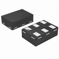
Package / Case
6-XSON (Micropak™), SOT-886
Voltage - Reverse Standoff (typ)
5V
Voltage - Breakdown
6.4V
Power (watts)
16W
Polarization
4 Channel Array - Unidirectional
Mounting Type
Surface Mount
Polarity
Unidirectional
Channels
4 Channels
Clamping Voltage
13 V
Operating Voltage
5 V
Breakdown Voltage
6.8 V
Peak Surge Current
1.5 A
Peak Pulse Power Dissipation
16 W
Capacitance
12 pF
Maximum Operating Temperature
+ 105 C
Minimum Operating Temperature
- 65 C
Dimensions
1.05(Max) mm W x 1.5(Max) mm L
Lead Free Status / RoHS Status
Lead free / RoHS Compliant
Lead Free Status / RoHS Status
Lead free / RoHS Compliant, Lead free / RoHS Compliant
Other names
568-4804-2
934061202115
PESD5V0V4UF T/R
PESD5V0V4UF T/R
PESD5V0V4UF,115
934061202115
PESD5V0V4UF T/R
PESD5V0V4UF T/R
PESD5V0V4UF,115


NXP Semiconductors
7. Application information
PESDXV4UF_G_W_3
Product data sheet
The devices are designed for the protection of up to four unidirectional data or signal lines
from the damage caused by ESD and surge pulses. The devices may be used on lines
where the signal polarities are both, positive and negative with respect to ground. The
devices provide a surge capability of 16 W per line for an 8/20 s waveform each.
Circuit board layout and protection device placement
Circuit board layout is critical for the suppression of ESD, Electrical Fast Transient (EFT)
and surge transients. The following guidelines are recommended:
1. Place the device as close to the input terminal or connector as possible.
2. The path length between the device and the protected line should be minimized.
3. Keep parallel signal paths to a minimum.
4. Avoid running protected conductors in parallel with unprotected conductors.
5. Minimize all Printed-Circuit Board (PCB) conductive loops including power and
6. Minimize the length of the transient return path to ground.
7. Avoid using shared transient return paths to a common ground point.
8. Ground planes should be used whenever possible. For multilayer PCBs, use ground
Fig 9. Application diagram
ground loops.
vias.
unidirectional protection of 4 lines
Rev. 03 — 28 January 2008
Very low capacitance quadruple ESD protection diode arrays
1
2
3
DUT
5
4
bidirectional protection of 3 lines
n.c.
PESDxV4UF/G/W
1
2
3
data- or transmission lines
DUT
006aab126
5
4
© NXP B.V. 2008. All rights reserved.
9 of 16
Related parts for PESD5V0V4UF,115
Image
Part Number
Description
Manufacturer
Datasheet
Request
R

Part Number:
Description:
NXP Semiconductors designed the LPC2420/2460 microcontroller around a 16-bit/32-bitARM7TDMI-S CPU core with real-time debug interfaces that include both JTAG andembedded trace
Manufacturer:
NXP Semiconductors
Datasheet:

Part Number:
Description:
NXP Semiconductors designed the LPC2458 microcontroller around a 16-bit/32-bitARM7TDMI-S CPU core with real-time debug interfaces that include both JTAG andembedded trace
Manufacturer:
NXP Semiconductors
Datasheet:
Part Number:
Description:
NXP Semiconductors designed the LPC2468 microcontroller around a 16-bit/32-bitARM7TDMI-S CPU core with real-time debug interfaces that include both JTAG andembedded trace
Manufacturer:
NXP Semiconductors
Datasheet:
Part Number:
Description:
NXP Semiconductors designed the LPC2470 microcontroller, powered by theARM7TDMI-S core, to be a highly integrated microcontroller for a wide range ofapplications that require advanced communications and high quality graphic displays
Manufacturer:
NXP Semiconductors
Datasheet:
Part Number:
Description:
NXP Semiconductors designed the LPC2478 microcontroller, powered by theARM7TDMI-S core, to be a highly integrated microcontroller for a wide range ofapplications that require advanced communications and high quality graphic displays
Manufacturer:
NXP Semiconductors
Datasheet:
Part Number:
Description:
The Philips Semiconductors XA (eXtended Architecture) family of 16-bit single-chip microcontrollers is powerful enough to easily handle the requirements of high performance embedded applications, yet inexpensive enough to compete in the market for hi
Manufacturer:
NXP Semiconductors
Datasheet:
Part Number:
Description:
The XA-S3 device is a member of Philips Semiconductors? XA(eXtended Architecture) family of high performance 16-bitsingle-chip microcontrollers
Manufacturer:
NXP Semiconductors
Datasheet:

Part Number:
Description:
The NXP BlueStreak LH75401/LH75411 family consists of two low-cost 16/32-bit System-on-Chip (SoC) devices
Manufacturer:
NXP Semiconductors
Datasheet:
Part Number:
Description:
The NXP LPC3130/3131 combine an 180 MHz ARM926EJ-S CPU core, high-speed USB2
Manufacturer:
NXP Semiconductors
Datasheet:
Part Number:
Description:
The NXP LPC3141 combine a 270 MHz ARM926EJ-S CPU core, High-speed USB 2
Manufacturer:
NXP Semiconductors
Part Number:
Description:
The NXP LPC3143 combine a 270 MHz ARM926EJ-S CPU core, High-speed USB 2
Manufacturer:
NXP Semiconductors

Part Number:
Description:
The NXP LPC3152 combines an 180 MHz ARM926EJ-S CPU core, High-speed USB 2
Manufacturer:
NXP Semiconductors
Part Number:
Description:
The NXP LPC3154 combines an 180 MHz ARM926EJ-S CPU core, High-speed USB 2
Manufacturer:
NXP Semiconductors

Part Number:
Description:
Standard level N-channel enhancement mode Field-Effect Transistor (FET) in a plastic package using NXP High-Performance Automotive (HPA) TrenchMOS technology
Manufacturer:
NXP Semiconductors
Datasheet: