PESD1CAN,215 NXP Semiconductors, PESD1CAN,215 Datasheet
PESD1CAN,215
Specifications of PESD1CAN,215
934059097215
PESD1CAN T/R
PESD1CAN T/R
Available stocks


Related parts for PESD1CAN,215


PESD1CAN,215 Summary of contents
Page 1
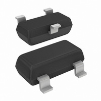
PESD1CAN CAN bus ESD protection diode Rev. 04 — 15 February 2008 1. Product profile 1.1 General description PESD1CAN in a small SOT23 (TO-236AB) Surface-Mounted Device (SMD) plastic package designed to protect two automotive Controller Area Network (CAN) bus lines ...
Page 2
... NXP Semiconductors 2. Pinning information Table 2. Pin Ordering information Table 3. Type number Package PESD1CAN 4. Marking Table 4. Type number PESD1CAN [ made in Hong Kong * = p: made in Hong Kong * = t: made in Malaysia * = W: made in China 5. Limiting values Table 5. In accordance with the Absolute Maximum Rating System (IEC 60134). ...
Page 3
... NXP Semiconductors Table 6. Symbol Per diode V ESD [1] Device stressed with ten non-repetitive ESD pulses. [2] Measured from pin Table 7. Standard Per diode IEC 61000-4-2; level 4 (ESD) MIL-STD-883; class 3 (human body model) 120 100 % (%) Fig 1. 8/20 s pulse waveform according to IEC 61000-4-5 PESD1CAN_4 Product data sheet ...
Page 4
... NXP Semiconductors 6. Characteristics Table unless otherwise specified. amb Symbol Per diode V RWM dif [ between pin 2 and pin 3. [2] Non-repetitive current pulse 8/20 s exponential decay waveform according to IEC 61000-4-5. [3] Measured from pin PESD1CAN_4 Product data sheet Characteristics Parameter Conditions reverse standoff voltage ...
Page 5
... NXP Semiconductors ( amb Fig 3. Peak pulse power as a function of exponential pulse duration; typical values (pF MHz amb Fig 5. Diode capacitance as a function of reverse voltage; typical values PESD1CAN_4 Product data sheet 006aaa257 P P PP( Fig 4. Relative variation of peak pulse power as a 006aaa258 (V) R Fig 6. V-I characteristics for a bidirectional ESD Rev. 04 — ...
Page 6
... NXP Semiconductors ESD TESTER IEC 61000-4-2 network C = 150 pF 330 Z Z GND unclamped 1 kV ESD voltage waveform (IEC 61000-4-2 network) GND unclamped 1 kV ESD voltage waveform (IEC 61000-4-2 network) Fig 7. ESD clamping test setup and waveforms PESD1CAN_4 Product data sheet RG 223/U 50 coax 450 D ...
Page 7
... NXP Semiconductors 7. Application information The PESD1CAN is designed for the protection of two automotive CAN bus lines from the damage caused by ESD and surge pulses. The device can be used for both, high-speed CAN bus and fault-tolerant CAN bus protection. The PESD1CAN provides a surge capability 200 W per line for an 8/20 s waveform ...
Page 8
... NXP Semiconductors 8. Package outline Fig 9. Package outline SOT23 (TO-236AB) 9. Packing information Table 9. The indicated -xxx are the last three digits of the 12NC ordering code. Type number Package PESD1CAN [1] For further information and the availability of packing methods, see PESD1CAN_4 Product data sheet 3 ...
Page 9
... NXP Semiconductors 10. Soldering Fig 10. Reflow soldering footprint SOT23 (TO-236AB) 4.60 Fig 11. Wave soldering footprint SOT23 (TO-236AB) PESD1CAN_4 Product data sheet 2.90 2.50 0.85 2 3.00 1.30 0.85 3 0.50 (3x) 0.60 (3x) 1.00 3.30 3.40 1.20 (2x 4.00 1.20 3 2.80 4.50 Rev. 04 — 15 February 2008 ...
Page 10
... NXP Semiconductors 11. Revision history Table 10. Revision history Document ID Release date PESD1CAN_4 20080215 • Modifications: Section 1.2 • Table 8 PESD1CAN_3 20070521 PESD1CAN_2 20051017 PESD1CAN_1 20050125 PESD1CAN_4 Product data sheet Data sheet status Product data sheet “Features”: list item for diode capacitance matching added “ ...
Page 11
... Right to make changes — NXP Semiconductors reserves the right to make changes to information published in this document, including without limitation specifications and product descriptions, at any time and without notice ...
Page 12
... NXP Semiconductors 14. Contents 1 Product profi 1.1 General description 1.2 Features . . . . . . . . . . . . . . . . . . . . . . . . . . . . . . 1 1.3 Applications . . . . . . . . . . . . . . . . . . . . . . . . . . . 1 1.4 Quick reference data Pinning information . . . . . . . . . . . . . . . . . . . . . . 2 3 Ordering information . . . . . . . . . . . . . . . . . . . . . 2 4 Marking . . . . . . . . . . . . . . . . . . . . . . . . . . . . . . . . 2 5 Limiting values Characteristics . . . . . . . . . . . . . . . . . . . . . . . . . . 4 7 Application information Package outline . . . . . . . . . . . . . . . . . . . . . . . . . 8 9 Packing information Soldering . . . . . . . . . . . . . . . . . . . . . . . . . . . . . . 9 11 Revision history . . . . . . . . . . . . . . . . . . . . . . . . 10 12 Legal information ...