MPC566EVB Freescale Semiconductor, MPC566EVB Datasheet - Page 12
MPC566EVB
Manufacturer Part Number
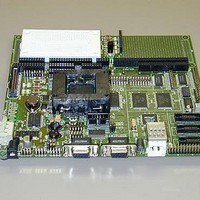
MPC566EVB
Description
KIT EVALUATION FOR MPC565/566
Manufacturer
Freescale Semiconductor
Specifications of MPC566EVB
Processor To Be Evaluated
MPC56x
Data Bus Width
32 bit
Interface Type
RS-232, Ethernet
Lead Free Status / RoHS Status
Contains lead / RoHS non-compliant


Freescale Semiconductor, Inc.
•Memory Devices:
1M Byte (256K x 32) Sync. SRAM
2M Byte (512K x 32) Sync. FLASH
1M Byte FLASH internal to MPC566 device
36K Byte SRAM internal to MPC566 device
•POWER OAK (PC33394 P2.6) regulated power supply for 5V, 3.3V and 2.6V supplies.
•MAP Switch – provides easy assignment of chip selects and memory mapping.
•CONFIG Switch – Basic necessary Reset Word Configuration options.
•COM1 - SCIA1 with RS232 type DB9-S Connection
•COM2 - SCIA2 with RS232 type DB9-S Connection, TX / RX polarity option.
•COM3 & 4 - SCIB1 and SCIB2 with RS232 type DB9-S Connection, 10 pin IDC ribbon header
connectors.
1
•CAN Ports
– 3 CAN transceiver interfaced ports, 1 x 4 headers.
•10/100T Ethernet Port – LAN91C111 based MAC+PHY, memory mapped.
•DEVELOPMENT Ports – Nexus 50 pin and dual voltage BDM Port.
•LCD Port - LCD Module Interface Connector w/ Contrast Adjust, Buffered and Memory
Mapped
1
•KEYPAD Port
- 16 Key passive interface, applies QADC_B channels for operation.
•BUS Port – 32 data and 24 address lines on 60 pin header.
•CONTROL Port - Bus Controls with 40 pin header.
•QSM Ports – 2 Serial I/O ports with 16 pin socket headers.
•MIOS Port - MDA, PWM, and MGPIO ports with 34 pin socket header.
1
•TPU Ports
- 3 Timing Processor I/O ports with 20 pin socket headers.
1
•QADC Ports
- 2 Analog I/O ports, one 20 pin and one 24 pin socket header.
•IRQ Port – Interrupt or MPC566 port I/O with 10 pin socket header.
•POWER Port – Primary and standby power supply access port, no header.
•I/O Connectors in .1 grid, pin headers for bus and control provide easy ribbon cable connection
for external connections. Socket headers provide easy wire connection to breadboard prototype
area with 22ga solid wire.
•Large Prototyping Area with +5V and ground connection grids.
•Mictor Logic Probe connectors for the Address and Data bus (Not installed default)
•Breadboard Prototyping area (2.5 x 1.5 inch) for easy installation of test connections.
•System Indicators – Reset Indicator, Supply voltage indications for 5V, 3.3V, and 2.6V supplies
•Reset Switches – POReset, Hard, Soft reset buttons.
•User Components – 4 user LEDs (one with debounce), 4 user Switches, 1 user Potentiometer
with socket header for I/O connection.
1
The MPC535/6 has limited or no functionality for this module. See Appendix A
1-2
MPC566EVB User’s Manual
For More Information On This Product,
Go to: www.freescale.com
Related parts for MPC566EVB
Image
Part Number
Description
Manufacturer
Datasheet
Request
R

Part Number:
Description:
Manufacturer:
Freescale Semiconductor, Inc
Datasheet:
Part Number:
Description:
Manufacturer:
Freescale Semiconductor, Inc
Datasheet:
Part Number:
Description:
Manufacturer:
Freescale Semiconductor, Inc
Datasheet:
Part Number:
Description:
Manufacturer:
Freescale Semiconductor, Inc
Datasheet:
Part Number:
Description:
Manufacturer:
Freescale Semiconductor, Inc
Datasheet:
Part Number:
Description:
Manufacturer:
Freescale Semiconductor, Inc
Datasheet:
Part Number:
Description:
Manufacturer:
Freescale Semiconductor, Inc
Datasheet:
Part Number:
Description:
Manufacturer:
Freescale Semiconductor, Inc
Datasheet:
Part Number:
Description:
Manufacturer:
Freescale Semiconductor, Inc
Datasheet:
Part Number:
Description:
Manufacturer:
Freescale Semiconductor, Inc
Datasheet:
Part Number:
Description:
Manufacturer:
Freescale Semiconductor, Inc
Datasheet:
Part Number:
Description:
Manufacturer:
Freescale Semiconductor, Inc
Datasheet:
Part Number:
Description:
Manufacturer:
Freescale Semiconductor, Inc
Datasheet:
Part Number:
Description:
Manufacturer:
Freescale Semiconductor, Inc
Datasheet:
Part Number:
Description:
Manufacturer:
Freescale Semiconductor, Inc
Datasheet: