DEMO9S08DZ60 Freescale Semiconductor, DEMO9S08DZ60 Datasheet - Page 14
DEMO9S08DZ60
Manufacturer Part Number
DEMO9S08DZ60
Description
BOARD DEMO
Manufacturer
Freescale Semiconductor
Type
MCUr
Datasheets
1.DEMO9S08DZ60.pdf
(416 pages)
2.DEMO9S08DZ60.pdf
(1 pages)
3.DEMO9S08DZ60.pdf
(16 pages)
4.DEMO9S08DZ60.pdf
(2 pages)
5.DEMO9S08DZ60.pdf
(1 pages)
Specifications of DEMO9S08DZ60
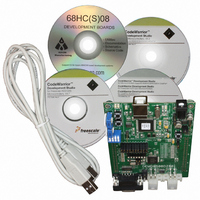
Contents
Board, Cable, CD
Processor To Be Evaluated
MC9S08DZ60
Interface Type
RS-232, USB
Silicon Manufacturer
Freescale
Core Architecture
HCS08
Core Sub-architecture
HCS08
Silicon Core Number
MC9S08
Silicon Family Name
S08D
Kit Contents
MC9S08DZ60 Board, Software, Cables, Connectors
Rohs Compliant
Yes
For Use With/related Products
MC9S08DZ60
Lead Free Status / RoHS Status
Lead free / RoHS Compliant


Table 5: ATD Reference Voltage
USER I/O
User I/O includes 2 potentiometers, 1 4-position DIP switch, 2 push button switches, and 2
green LEDs for user I/O. The User option header block enables or disables each User I/O
individually.
POT
The DEMO9S08DZ60 target board provides 2 5K ohm trimmer potentiometers (POT) have
been provided to simulate analog input. Both parts are decoupled to minimize noise during
adjustment. Potentiometer RV1 connects to analog input PTB4/ADP12. Potentiometer RV2
connects to analog input PTB5/ADP13. . The figure below shows the USER enable position
and associated signal for the potentiometer.
SWITCHES
The DEMO9S08DZ60 target board provides 2 push button switches and one 4-position DIP
switch for user input. Each push button switch is an active low input with a pull-up resistor bias
to prevent indeterminate input conditions. Pressing a push-button switch causes a low logic
input on the associated input.
Each DIP switch position is an active low input. Use of the DIP switches requires enabling the
associated, internal PORTG pull-ups on the MCU prevent indeterminate input conditions.
Moving a DIP switch position to ON causes a low logic level on the associated input. The
figure below shows the USER enable position and associated signal for each user switch.
LED’s
The DEMO9S08DZ60 target board provides 2 green LEDs for output indication. Each LED is
an active low output. Writing a low logic level to an LED output causes the associated LED to
turn on. A series, current-limit resistor prevents excessive diode current. The figure below
shows the USER enable position and associated signal for each user LED.
User Signals
The following table shows the connections for each user I/O device.
NOTE: Damage to the board may result if an alternate reference voltage is attached without
R25
R26
first removing the associated configuration resistor.
VRH = VDD
VRL = GND
Installed (Default)
VRH provided by user
VRL provided by user
Removed
14
Related parts for DEMO9S08DZ60
Image
Part Number
Description
Manufacturer
Datasheet
Request
R

Part Number:
Description:
Manufacturer:
Freescale Semiconductor, Inc
Datasheet:
Part Number:
Description:
Manufacturer:
Freescale Semiconductor, Inc
Datasheet:
Part Number:
Description:
Manufacturer:
Freescale Semiconductor, Inc
Datasheet:
Part Number:
Description:
Manufacturer:
Freescale Semiconductor, Inc
Datasheet:
Part Number:
Description:
Manufacturer:
Freescale Semiconductor, Inc
Datasheet:
Part Number:
Description:
Manufacturer:
Freescale Semiconductor, Inc
Datasheet:
Part Number:
Description:
Manufacturer:
Freescale Semiconductor, Inc
Datasheet:
Part Number:
Description:
Manufacturer:
Freescale Semiconductor, Inc
Datasheet:
Part Number:
Description:
Manufacturer:
Freescale Semiconductor, Inc
Datasheet:
Part Number:
Description:
Manufacturer:
Freescale Semiconductor, Inc
Datasheet:
Part Number:
Description:
Manufacturer:
Freescale Semiconductor, Inc
Datasheet:
Part Number:
Description:
Manufacturer:
Freescale Semiconductor, Inc
Datasheet:
Part Number:
Description:
Manufacturer:
Freescale Semiconductor, Inc
Datasheet:
Part Number:
Description:
Manufacturer:
Freescale Semiconductor, Inc
Datasheet:
Part Number:
Description:
Manufacturer:
Freescale Semiconductor, Inc
Datasheet: